Setting up a BACnet Studio project
Follow these steps and start building your i4BACnet project using the i4scada Studio application.
The purpose of this tutorial is to exemplify how to set up a BACnet Studio project.
Configure the BACnet Connector as described in the article Connector Configuration
As soon as BACnet Connector has been configured, proceed with setting up Alarm Groups, Alarm Types, Alarm Conditions, and Alarms, under the Alarming section of Studio. More details on the i4scada Alarms configuration may be found in this article.
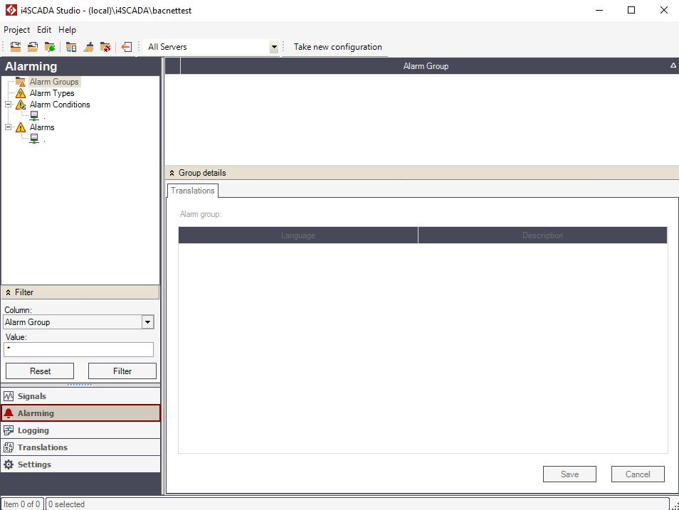
Alarming section of Studio
Right-click on the Alarm Groups node in the tree menu or inside the alarm groups view and select option New.
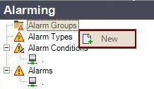
New Alarm Group
Provide name and description for the new Alarm Group, for all languages defined in the system (by default German and English). Translations may be added using the Group Details panel.
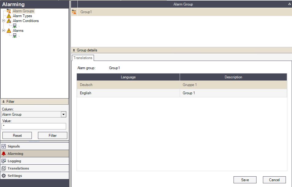
Name and description of new Alarm Group
To store the new Alarm Group click on the Save button.
Select the Alarm Types node and by means of right-click node, select option New.
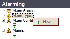
New Alarm Type
Name your new alarm type and provide descriptions for all the languages defined in the system (by default German and English). The description translations are added using the Type Details panel.
Enable or disable the Automatic alarm acknowledgment for this type of alarm. If enabled, the alarms will be acknowledged by the system as they appear.
To preserve the changes made for the new Alarm Type, click on the button Save.
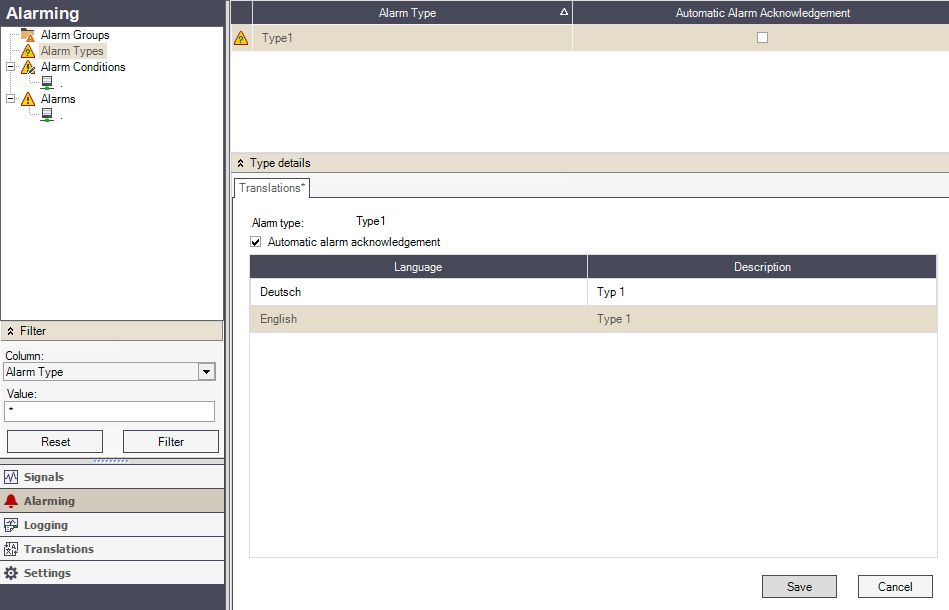
Save new created Alarm Type
Proceed with the creation of Alarm Conditions under the respective node in the Alarming tree menu, via right-click and selection of button New.
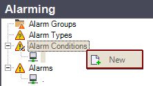
New Alarm Condition
Fill in the Name of the new Alarm Condition.
Select the logical condition for triggering the alarm, under the Criteria field
Enter a Constant value that will be used in equating the state of the Criteria.
Enter, if required by the selected Criteria, a Constant to value, that will be used in equating the state of range-based Criteria.
Select a Signal that will be used in equating the state of certain Criteria that requires another signal value for comparison.
Preserve the changes made by clicking the button Save
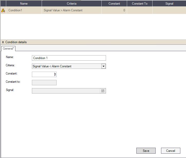
Alarm Condition Details
Further on, click on the Alarms node in the tree menu or inside the alarm view and select New.
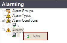
New Alarm
In the Signal Browser, select the signal that will be monitored and will trigger the alarm if the conditions match.
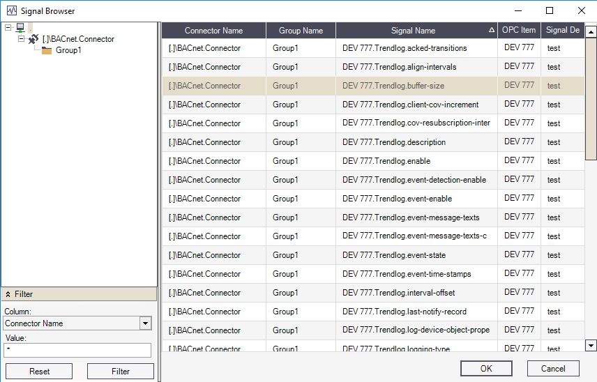
Signal Browser
The new alarm will have predefined settings applied. Use the Alarm Details panel to set up the alarm as required for your scenario.
Press the button Save to store the new Alarm.
Switch from Alarming to Logging section. More details on Logging functionality may be found in this article.
Right-click on the Log Conditions node in the tree menu or inside the log conditions view and select New.
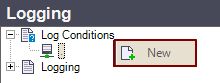
New Log Conditions
Fill in Name for the new Log Condition
Under Log Conditions, details fill in the Log Mode selecting from the drop-down list
Depending on the selected Log Mode, Log Interval, Log Constant, Signal Value 2 , and Report Interval may also be defined
Store the changes by pressing the button Save
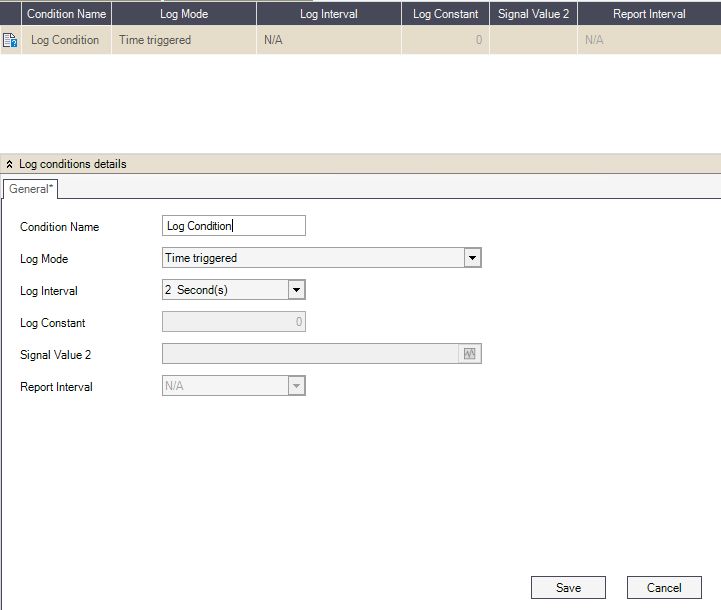
Log Condition details
Right-click on the Logging node in the tree menu or inside the logging view and select New.
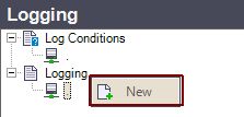
New Logging
In the Signal Browser, select the signal that will be logged using this definition.
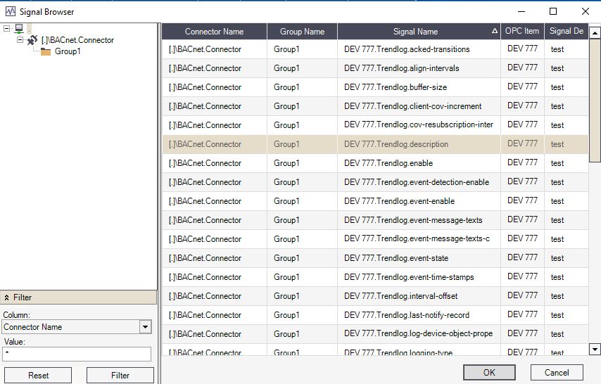
Signal Browser
Activate the new log so that it's taken into account by the i4scada Server.
Name your new log using the Log Tag field.
Enter the number of days to keep the log before purging, using the Max Days option. The first logged value reaching this specified age will be deleted when a new value is stored.
Enter the maximum number of logs to be stored, using the Max Numbers option. Once this number is reached, the oldest logged value will be deleted when a new one is stored.
Enter the name of the database where the logs will be stored, using the Log Database field. If no database is specified, the logs will be stored in the default project database, inside the dedicated table.
Enable the IoT option if this log must be accessed using the IoT Hub.
Preserve the changes by clicking the button Save.
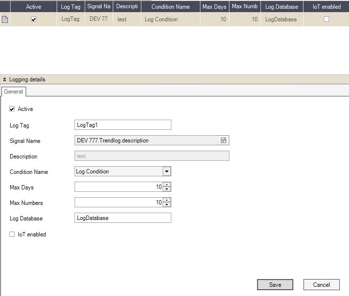
Logging details
Switch to the Translations section in order to define any necessary translations. More details upon project translations may be found in this article.
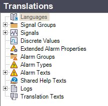
Translations tree menu
Further project settings may be organized under the Settings section. Read more about the potential settings, in the i4scada documentation under i4scada Studio Settings area and i4scada Studio User Manager.
After following up and organizing all the above-indicated steps, your Studio Project is prepared for proper BACnet Connector usage.