HMI Platform
Check out this article in order to learn more details about the particularities of the OPC-UA platform included in the i4Designer environment.
Quite similar to the i4scada platform projects, the project created on the OPC-UA platform (HMI) allows the user with the possibility to design and visualize projects using an OPC-UA server. Hence, this platform features the following particularities:
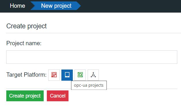
i4designer project for the OPC-UA platform
OPC-UA Project settings
By clicking the Settings menu of the Designer contextual actions area, the OPC-UA project settings panel is opened.
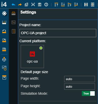
The OPC-UA Project settings panel
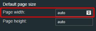
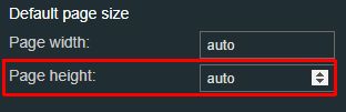
In this view, a set of project general information is displayed, along with the possibility to customize the deployment screen size:
Width - specifies the width of the screen size for both design-time and run-time. The screen width can be adjusted by directly typing in the desired value or by using the up / down arrows to increase or decrease it.
Screen width
Height - specifies the height of the screen size for both design-time and run-time. The screen height can be adjusted by directly typing in the desired value or by using the up/down arrows to increase or decrease it.
Screen height
Simulation Mode - allows the user to turn on and off the signal simulation, per project. When the Signal Simulation Mode is set to True all the components using Signals data will simulate values at design time, therefore allowing the user to test a project while designing it. By default, the property is set to True.
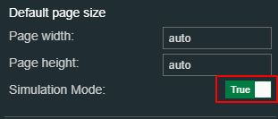
Simulation Mode
OPC-UA Components
The OPC-UA platform shares its components list with the i4scada platform, hence the user can design projects using all components available under the Toolbox panel.
Warning
Components that are not compatible with the OPC-UA platform projects are disabled from the Toolbox.