i4designer Signals tutorials
Check out the signals simulation functionality allowing you to test your visualization project while designing it, hence saving valuable engineering time.
From i4designer point of view, the signals are assets that are present in the project itself. Each project can have its own set of signals that can be either imported from using an XML file or directly synchronized from your database.
In order to avoid a direct connection between i4designer and i4scada or i4connected servers, the signals in i4designer are capable to trigger simulated values. Based on the i4designer provided signal simulation patterns, it is possible to test every scenario that you might have, by tweaking the simulation patterns and see actual state updates. This way, the designed project can be tested before actually publishing the project without risking real data corruption.
After publishing your project and opening the visualization, the online signals will be applied.
Tip
For more details about the Signals menu and its particularities check out the article here.
Importing signals from an XML file
Check out this tutorial and learn how to import signals to your i4designer project from an XML file, obtained directly from your i4scada project.
In order to import your signal to an i4designer project, please follow the below-described steps:
Open your i4designer project and click on the Signals menu of the global actions area. The Signal operation panel and the Signal Configuration page are opened.
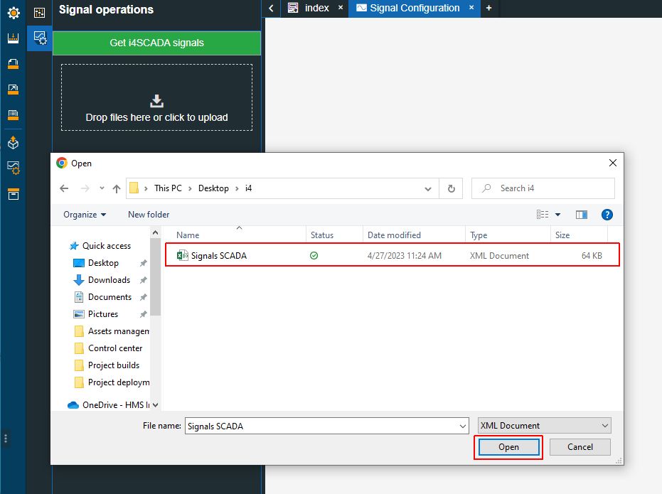
Click on the Signal import designated area in order to open the files explorer window.
Select the XML file containing the signals to be imported and click the Open button to upload them to your project.
The Signals import area is updated to display the uploaded XML file. In this view, the user can choose between Replace and Merge import behaviors.
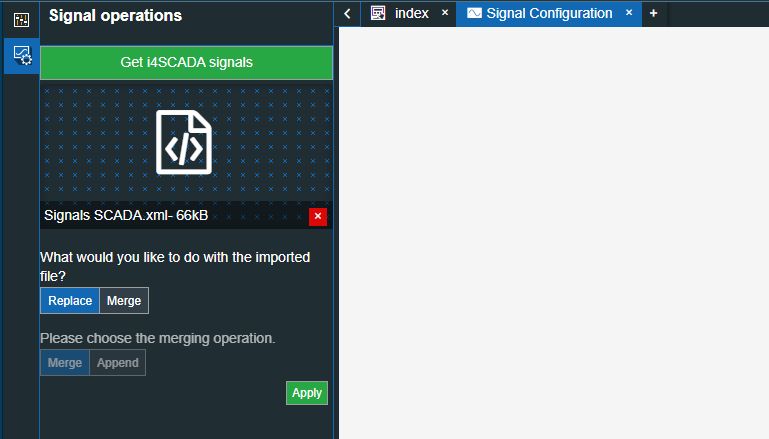
Click the Apply button to proceed with the Signals import action.
The Signal Configuration page is updated to display the list of all uploaded Signals providing a set of available information about them.
Synchronizing signals from an i4connected database
Check out this tutorial and learn how to get signals from an i4connected database directly into your i4designer project and use them for simulation purposes.
In order to synchronize signals from your i4connected database and reuse them for simulation purposes in the Designer, please follow the below described steps:
Warning
The option to synchronize Signals from an i4connected database is active, only for projects running on an Active synchronization mode.
Since Signals synchronization for i4connected environments, running on Passive synchronization
For more details about Signal synchronization, from i4connected environments, running on Passive synchronization, please also read the dedicated article, available in the i4connected knowledge base.
Open your i4designer project and click the Settings menu of the global actions area.
Tip
For more details about the Settings menu please also check the respective article here.
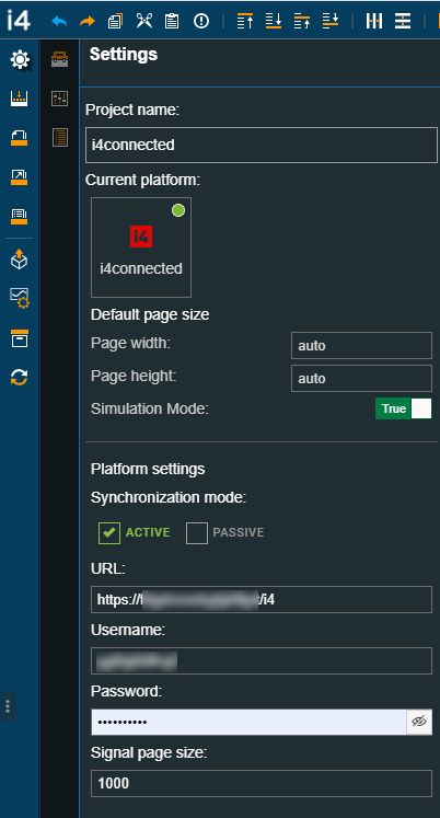
In the Settings panel, fill in the Platform settings.
Tip
For more details about the Platform settings please also check the i4connected Plaform article.
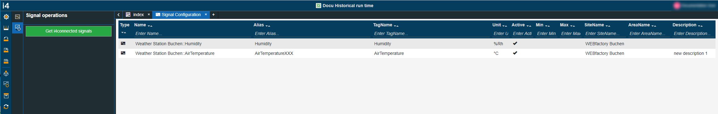
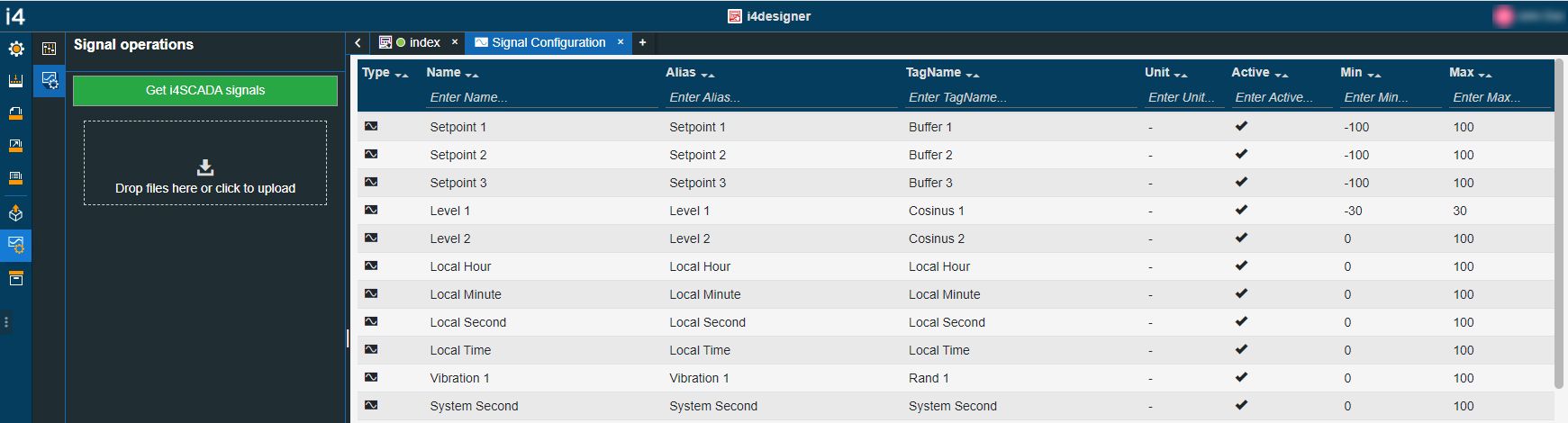
Next, open the Signal configuration menu of the global actions area. The Signal operations panel and the Signal Configuration page are opened.
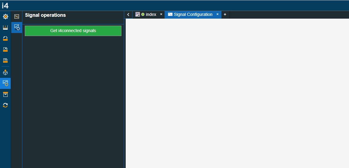
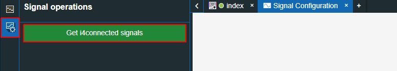
Click on the Get i4connected signals button.
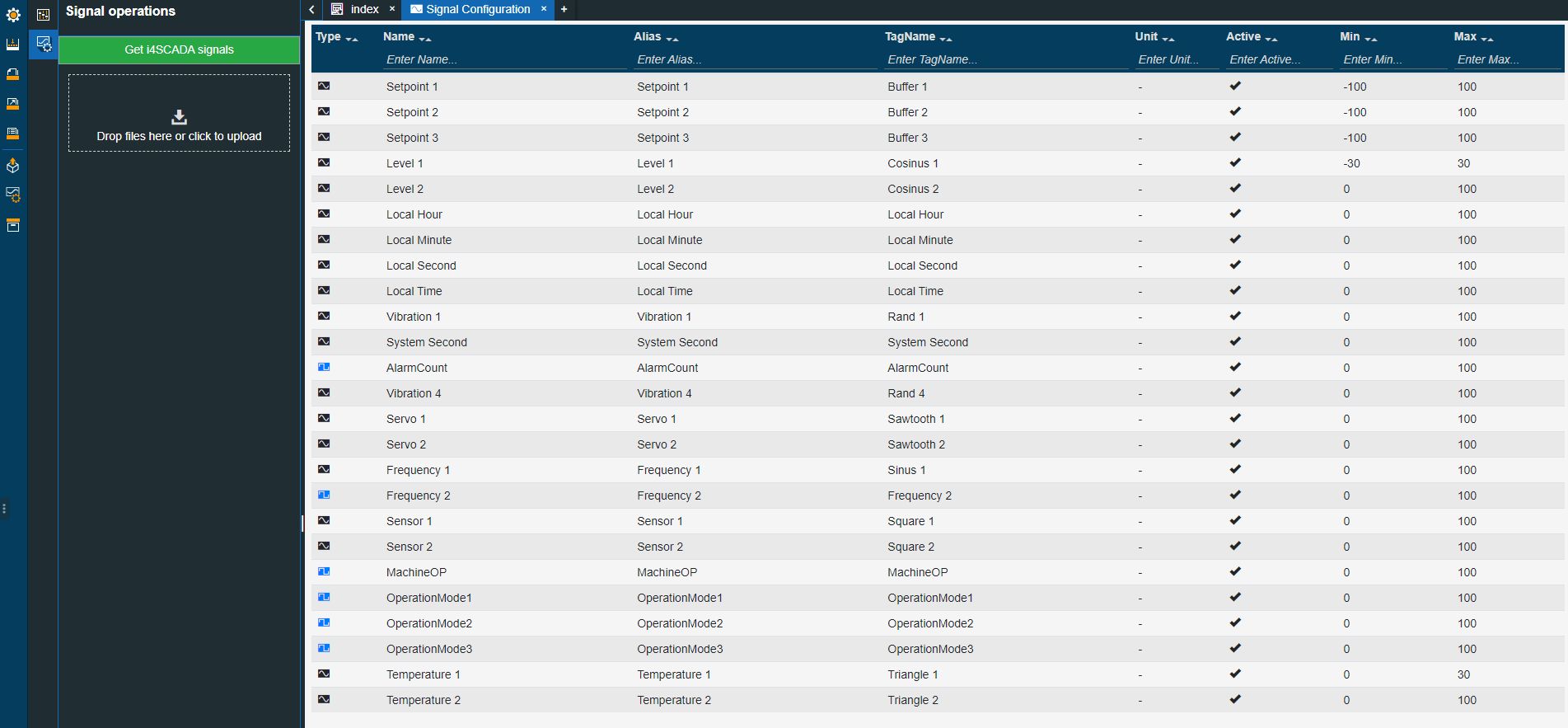
The Signal Configuration page is populated with all the Signals available in the pre-configured platform.
Synchronizing signals from an i4scada database
Check out this tutorial and learn how to get signals from an i4scada database directly into your i4designer project and use them for simulation purposes.
In order to synchronize signals from your i4scada database and reuse them for simulation purposes in the Designer, please follow the below-described steps:
Open the i4scadaStudio application.
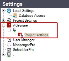
Select the Settings menu and expand the i4designer node, until reaching the Project settings node.
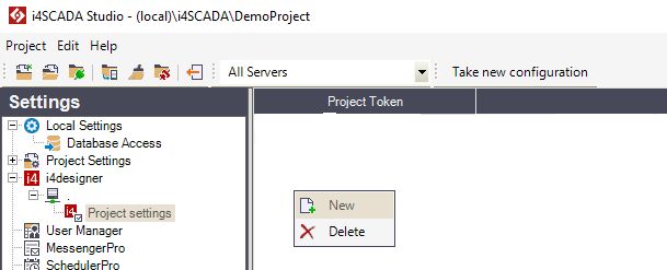
Right-click within the Project settings empty panel and select the option New.
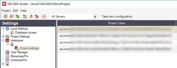
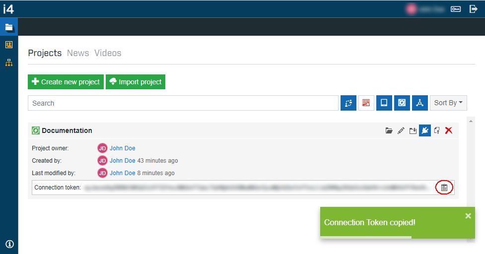
The Project settings panel is updated and allows you to fill in the Project Token. Fill in the Project Token after copying it from the application.
Tip
Each project has an allocated connection-token. This can be easily copied from the Control Center, as visible in the screenshot below.
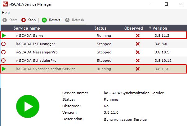
After filling in the Project settings, make sure that the Server and the Synchronization Service are running.
Next, open your i4designer project, in design-mode.
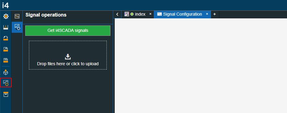
Open the Signal configuration menu of the global actions area. The Signal operations panel and the Signal Configuration page are opened.
Click on the Get i4scada signals button.
The Signal Configuration page is populated with all the Signals available on your i4scada server.
Testing states updates in signal simulation mode
Check out this tutorial and learn how to test your component's state updates by tweaking the signals simulation patterns.
As previously indicated, the i4designer Signals are assets that only show simulated values. The present tutorial will guide you through a set of steps that will demonstrate to you how to use the signal simulation functionality to test your project while in the design phase.
Note
The present demonstration will use the Signals imported from the default Ewon by HMS Networksi4scada Demo project.
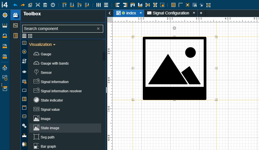
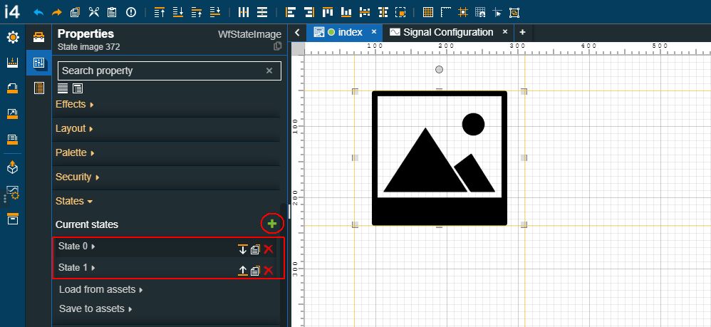
Open an i4designer project and drag on the project page the State image component.
Make sure that your project is populated with Signals, under the Signal configuration menu under the global actions area.
Select a Signal from the Signal Configuration page and double-click on it. The Signal simulation panel for the selected signal will be opened.
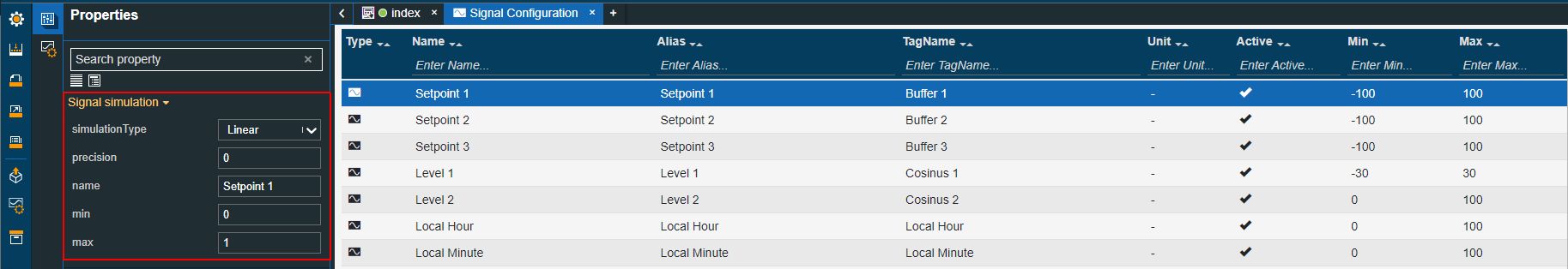
In the Signal simulation panel define the signal simulation patterns.
Tip
For the present tutorial, we selected the Setpoint 1 signal and updated its properties as follows:
Set property Max to 1.
Set property Min to 0.
Set Simulation Type to Linear.
For more details about the Signal simulation patterns check out the article describing them.
Return to your project page where the State image component was added and double click on it to open its properties.
In the State image properties panel, organize the following changes:
Add two new States for the component.
Expand the properties of the first state and set the Condition rule, the Image, and the Symbolic Text.
Tip
For the present tutorial we selected the following properties :
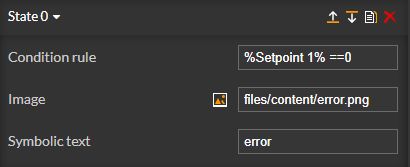
Condition rule - %Setpoint 1% ==0
Image 1
Symbolic text - Error
Expand the properties of the second state and set the Condition rule, the Image, and the Symbolic Text.
Tip
For the present tutorial we selected the following properties :
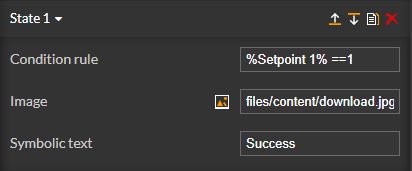
Condition rule - %Setpoint 1% ==1
Image 2
Symbolic text - Success
As soon as the two states have been defined, the State image component will start changing the images based on the signal simulated value change.
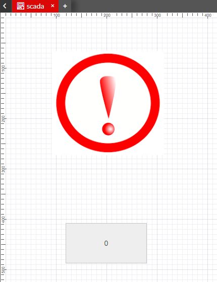
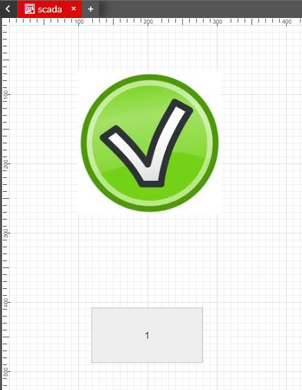
State image component changes image based on the Signal value
Using the Signal List component to manage online Signal values
Check out this article and learn more details on how to view signal values in your visualizations, using the Signal List component.
The Signal List component is a collection of numeric and textual display extensions that can display signal values with labels and icons.
Depending on the design-time configuration, the Signal List component allows the users the possibility to read and write online Signal values in i4designer visualizations.
Adding Signals at design-time
The i4designer component allows the user the possibility to add Signals at design-time, as follows:
Open an i4designer project in design mode. For the present tutorial, we shall use an i4scada platform project.
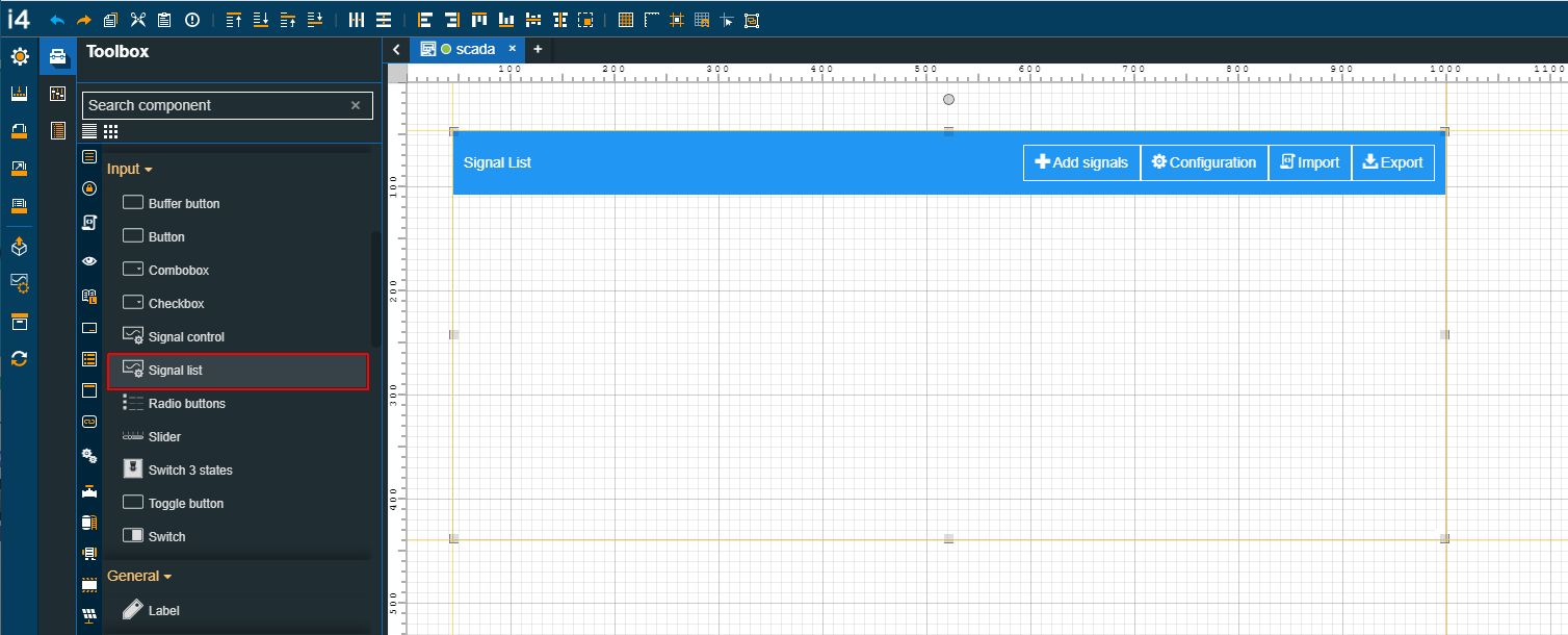
Go to the Toolbox panel in the contextual actions area, drag the Signal List component to your project page and proceed as follows:
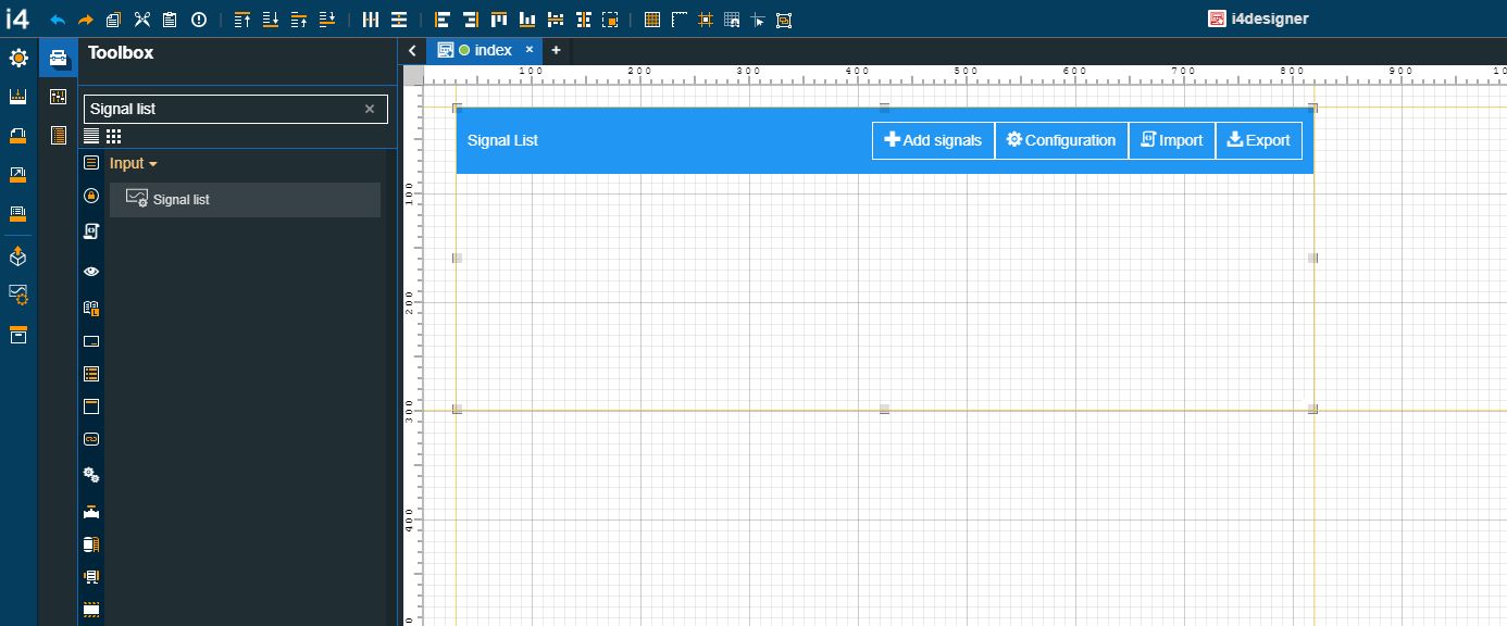
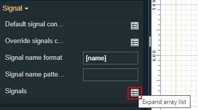
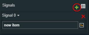
Expand the Signals property, under the Signal category, by clicking the Expand array list button.
To add signals to the configuration click the Add new item button. The view is expanded to display one new Signal item.
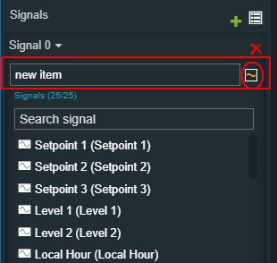
In the signal item area, you can either type in the name of your Signal, or you can use the Signal browser panel to select it from the list view.
Tip
The list of design-time Signals can be populated by adding Signals to your i4designer project. For more details on how to add Signals to a Designer project, please visit the dedicated tutorials, here.
Next, expand the Default signal configuration property, in the Signal category, and set the desired signal configuration.
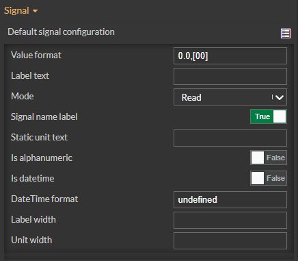
Important
The settings of the Default signal configuration properties will be applied to all the Signals in the list.
Tip
For more details about each Default signal configuration property please read the dedicated article, here.
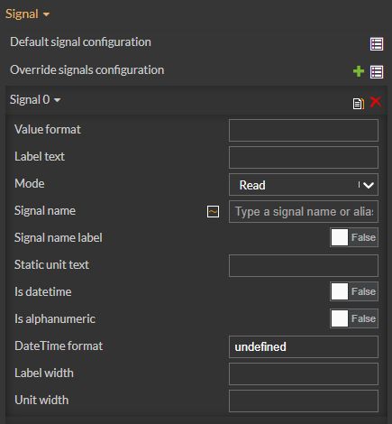
To override the Default Signal configuration properties, for one or multiple Signals, expand the Override signals configuration property, under the Signal category. Select your desired configurations.
Tip
For more details about each Default signal configuration property please read the dedicated article, here.
Make sure your changes are saved.
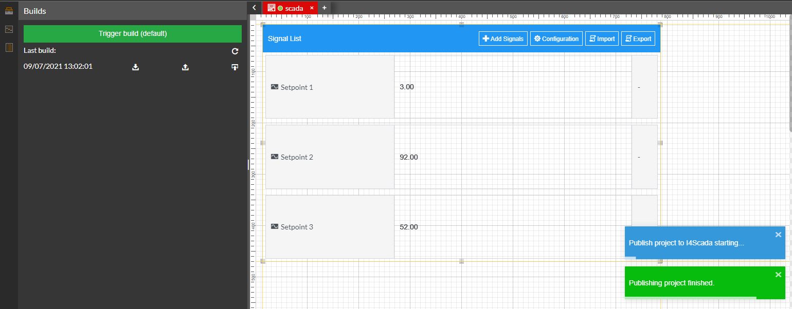
Build and publish your project.
Tip
For more details about i4scada platform deployments, please visit the dedicated tutorials here.
If your project is targeting an i4connected environment, please read more details about i4connected platform details, please visit the dedicated article here.
Access your target environment and open the visualization containing your i4designer project.
The Signal List component is displayed and all the previously configured Signals are visible.
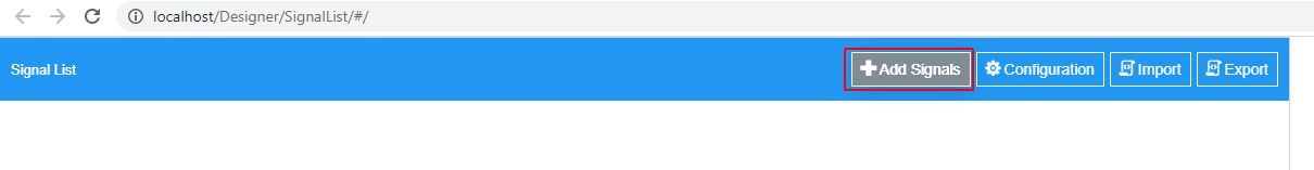
To populate the list of Signals, click the Add Signals button.
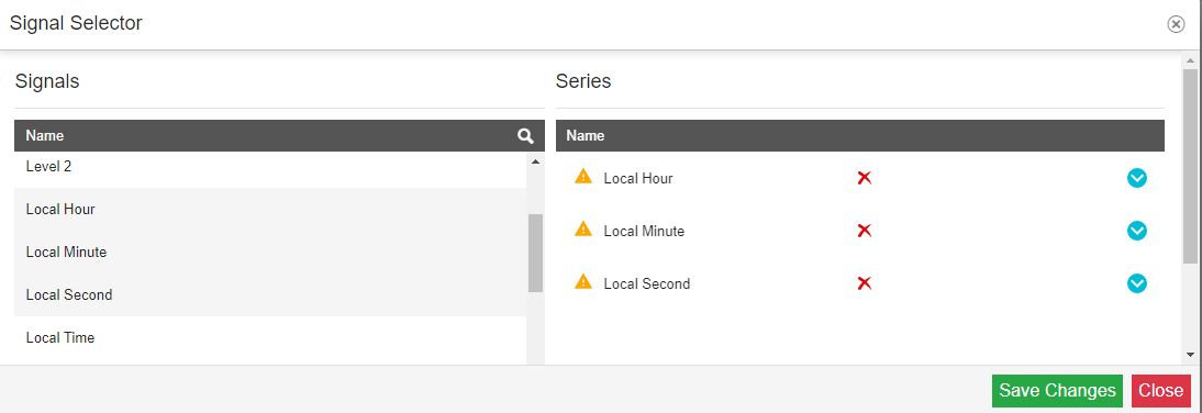
Using the Signal Selector dialog, select the desired Signals. Once the signals are selected, they will be displayed in the Series list. To confirm your selection click the Save Changes button.
The Signal List is populated with the selected Signals. The list is spread through three columns: The Signal name, the Signal value, and the Signal unit.
The listed Signals expose their current value, and any changes at the Signal value level will be displayed in this view.
Adding Signals at run-time
The Signal List component allows you the possibility to add Signals in your visualization, regardless if there were no Signals configured at design time. Please follow the steps below:
Open an i4designer project in design mode. For the present tutorial, we shall use an i4scada platform project.
Go to the Toolbox panel in the contextual actions area, drag the Signal List component to your project page. Since our goal is to add Signals to the list at run-time, we shall leave the default settings on.
Build and publish your project.
Tip
For more details about i4scada platform deployments, please visit the dedicated tutorials here.
If your project is targeting an i4connected environment, please read more details about i4connected platform details, please visit the dedicated article here.
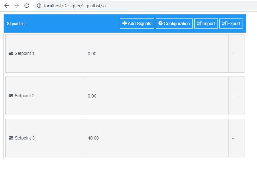
Access your target environment and open the visualization containing your i4designer project.
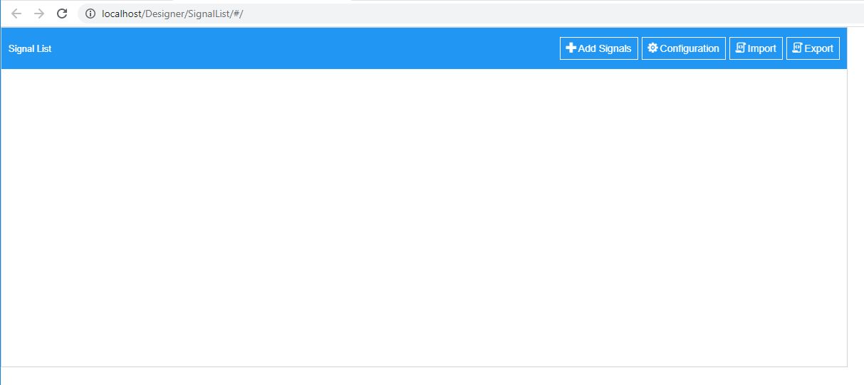
The Signal List component is displayed. Since no Signals were added at design time, the list will be empty.
To populate the list of Signals, click the Add Signals button.
Using the Signal Selector dialog, select the desired Signals. Once the signals are selected, they will be displayed in the Series list. To confirm your selection click the Save Changes button.
The Signal List is populated with the selected Signals. The list is spread through three columns: The Signal name, the Signal value, and the Signal unit.
The listed Signals expose their current value, and any changes at the Signal value level will be displayed in this view.
Writing Signal values
To write new values to your Signals, please proceed as follows:
Open an i4designer project in design mode. For the present tutorial, we shall use an i4scada platform project. You can either add your Signals at design time or at run time.
Expand the Default signal configuration property, in the Signal category, and set the Mode property to value ReadWrite.
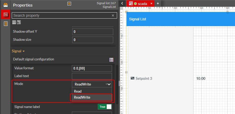
Tip
You can set the ReadWrite mode for specific Signals only, under the Override signals configuration properties.
Build and publish your project.
Tip
For more details about i4scada platform deployments, please visit the dedicated tutorials here.
If your project is targeting an i4connected environment, please read more details about i4connected platform details, please visit the dedicated article here.
Access your target environment and open the visualization containing your i4designer project.
The Signal List component is displayed.
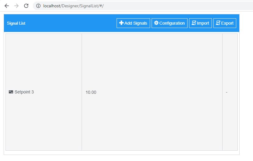
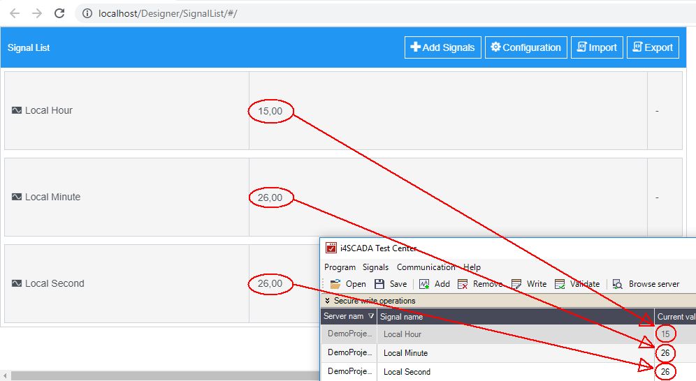
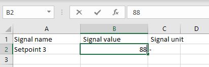
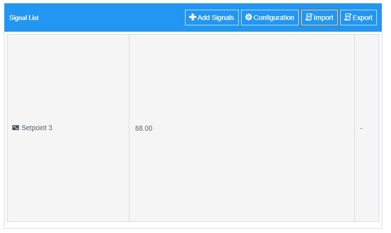
To change the current Signal value, click in the Signal value area and type in the new value.
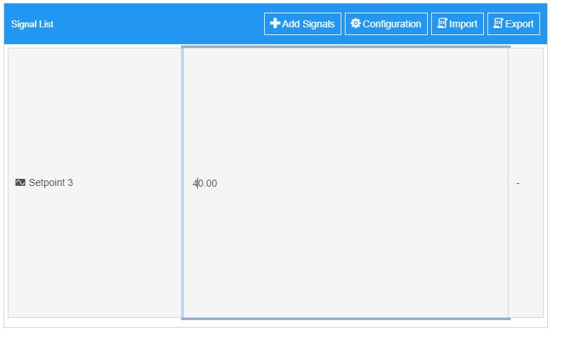
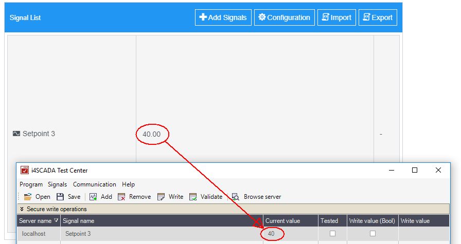
The Signal update is done and the new value will now be displayed.
Exporting Signals
You can obtain an output of the Signals list as follows:
Click the Export toolbar button. The exported content will be saved on your local machine, to a storage location of your choice.
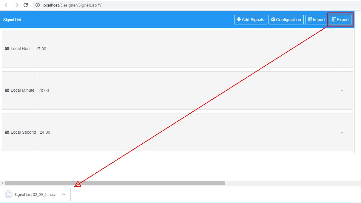
The Signal list document is saved in CSV format.
Importing Signal values
The Import function of the Signal List component allows you to write multiple Signal values, for a list of already configured Signals, as follows:
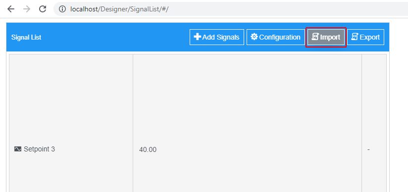
Click the Import button.
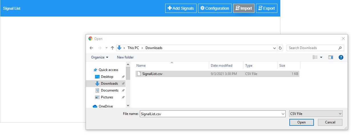
The Open dialog is opened, allowing you to browse for the import file, on your local computer.
Important
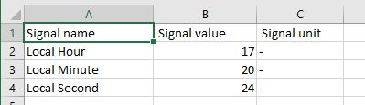
The import file needs to be a CSV file, that you can manually update before
After finding the desired import file, click the Open button. The Import will take place in the system's background. As soon as it is finished the new values will be displayed in the Signal List.
Warning
Since the import function only allows Signal value updates, if any new/unknown Signal is found in the import file it will be ignored. Only the Signals available in the Signal List will be updated.
Save and Load predefined configurations
Previous configurations at the level of the Signal List component can be stored and reused, as follows:
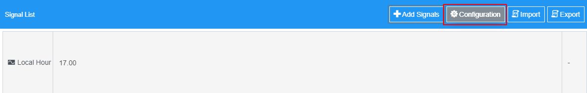
Click the Configuration toolbar button.
The Configuration window is opened, displaying the following areas:
The Add / Import new configuration area features an easy method to define new configurations or to update the existing configurations, by typing in the name of the configuration and clicking the Add / Update button. The Import new configuration allows you to browse for the import file, from your local computer.
Tip
There can not be multiple configurations with the same name, for the same component. In an attempt to add a duplicate configuration, the Add button, displayed in the Add new configuration section, is changed into an Update button.
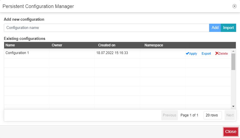
The Existing configurations area lists all the configurations, available for the Alarm viewer. The Existing configurations table features the following columns:
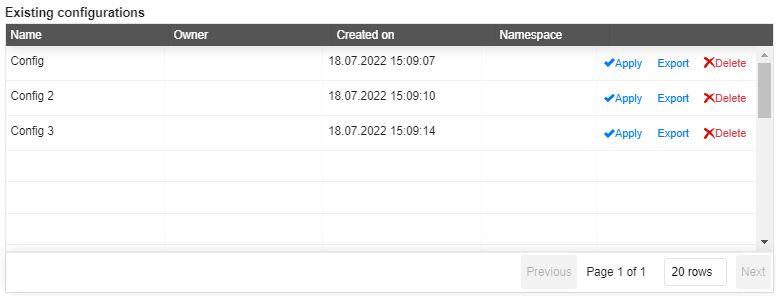
Name - the name of the component configuration, provided by the creator user, at the moment of creation. There cannot be multiple configurations with the same name, in the context of one single component.
Owner - the user that owns the component configuration.
Created On - the creation date.
Namespace - the value of the Namespace property, as defined at design-time.
Actions - the actions available for the selected configuration. The scope of the Actions area is to allow the user to either load configurations or remove them.
The Apply button enforces the selected configuration to the component. As soon as an existing configuration is applied, the Configurations window is closed and the component is updated according to the configurations
The Export button exports the configuration on your local machine, to a storage location of your choice.
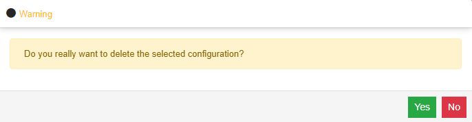
The Delete button removes the selected configuration.
As soon as an existing configuration is selected and the user clicks the Delete button, a confirmation dialog pops up asking for the user decision (Yes / No buttons).