i4scada Modbus Connector Tutorials
Check out these tutorials and start setting up your i4scada Studio Modbus Connector. All the details you need to know in order to do these steps by yourself.
These articles will guide the user through the steps needed to define a Modbus Connector and explain how to setup it up in order to receive data.
Configuring the Modbus Connector in i4scada Studio
Check out this easy guide and start setting up your i4scada Modbus Connector on your Studio Database.
To enable i4scada Server to access a Modbus device, the Modbus Connector must be added in Studio.
Open the i4scada Studio application.
The login dialog is opened. Fill in your credentials (if you are a new user and made no changes during i4scada installation, the default user name is "webfactory" and the password is "sa".
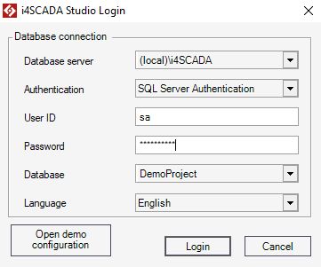
Select the [New Database] option from the Database drop-down list.
The New Database dialog is opened, allowing the user to fill in the Database name.
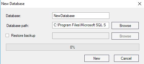
Press the button New to start generating the new Database.
Once the Database is prepared, press the Login button.
The i4scada Studio is opened. An information window pops up asking the user to confirm if the new database should be set as the Default or not.
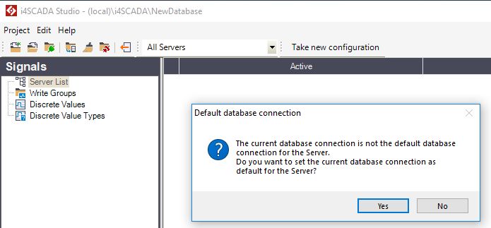
For the current use case, we shall set the New database as default, hence button Yes should be selected.
Under the Signals section click right on the Server List node.
The Server contextual dialog is displayed. Select the option New Server.
A new Server node is added, under Server List. We shall name the new Server ".", as for the current use case, the Server runs on the same machine as the i4scada Studio.
Select the Server node and click-right. Select the option New Connector / Modbus Connector from the contextual menu.
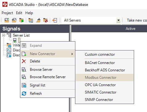
The Modbus Connector node is added to the hierarchical view.
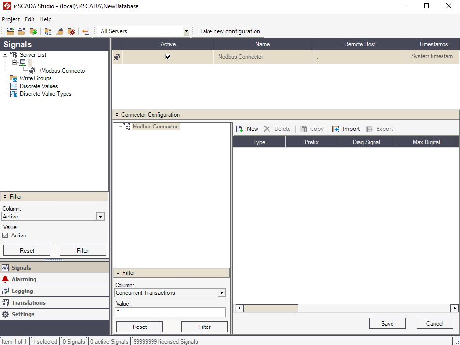
Further configuration steps, will be organized in the Connector Configuration panel.
Select the Modbus Connector node and click the toolbar button New.

Select the desired communication protocol choosing from the available options: TCP or RTU.
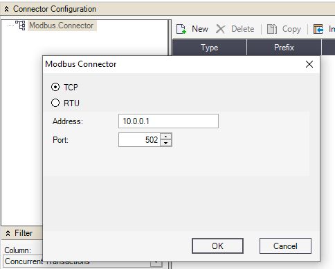
The new Device will be added to the Connector, allowing you to set it up in the grid view.

Select the new Device in the hierarchical view and click the button New.

A new substation is added to the hierarchical view, along with the available data types.
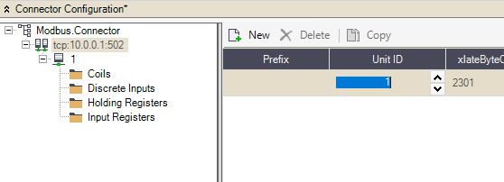
Select a data type in the hierarchical view and click the button New.

A new Signal is added in the data Type grid view, allowing you to set it up its properties. Continue adding as many Signals as necessary.

Press the Save button in order to preserve all your changes.
Setting up a Signal for the Modbus Connector
In order to create a new signal in the Modbus Connector, we need to create first a new signal group in our connector. Check out this tutorial to learn more.
Now the Modbus Connector is configured and connected to its Device, we need to create a signal group in our connector. Proceed as follows:
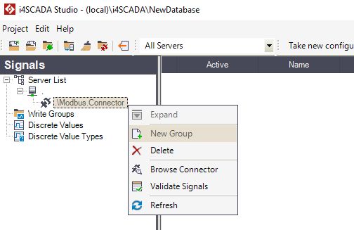
Select the connector from the Signals tab / Server List / Server and right click in the empty pane from the right side. Select New Group.
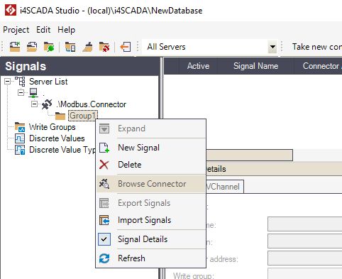
Now select the new group Group1 from the Signal tab / Server List / Server i4scada Modbus Connector and right click on it. Select the Browse Signal option.
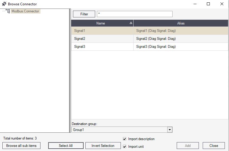
In the Browse connector window, the Modbus Device Signals are listed.
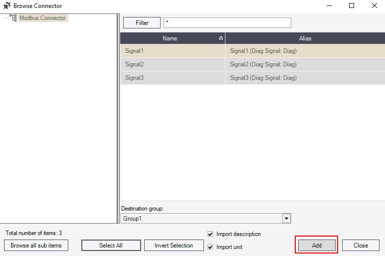
Select the desired Signals and click the button Add to confirm and upload selected items. Afterward, you click the Close button to close the Browse connector window,
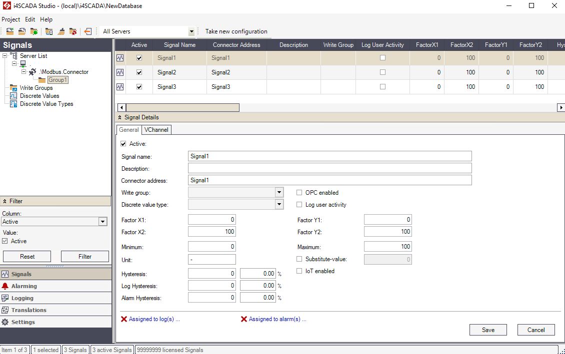
Now the list of i4scada Modbus Connector Signals is populated with all the selected items. To preserve your changes, click the Save button.
Validating the Modbus Signals
Check out how to use the i4scada Studio validation function in order to validate your Modbus Signals and see if there are any invalid ones.
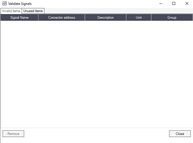
i4scada Studio provides a validation function that helps in determining whether invalid signals have been configured for a specific connector or symbols provided by the connector are not used.
Select the Modbus Connector node in the Signals panel and click right on it. Select the Validate Signals option.
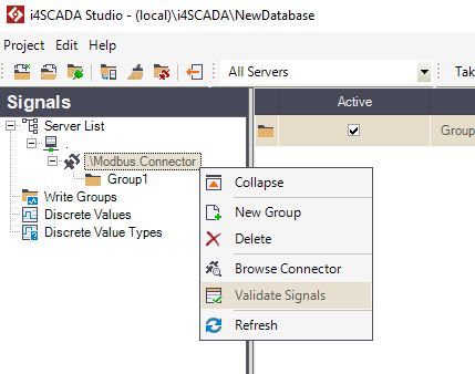
The Validate Signals will list the invalid signals or unused symbols if they exist.
