i4scada SNMP Connector Tutorials
Check out these tutorials and start setting up your i4scada Studio SNMP Connector. All the details you need to know in order to do these steps by yourself.
These articles will guide the user through the steps needed to define a SNMP Connector and explain how to setup it up in order to receive data.
In these tutorials, we will use the SNMP Connector inside i4scada Studio to connect to the local machine and get the number of running processes, using the OID value obtained from a MIB browser.
Note
Currently, i4scada only supports V1 and V2 of an SNMP protocol. V3 is not supported yet.
Configuring the SNMP Connector in i4scada Studio
Here are the steps needed to ad the SNMP Connector to your i4scada Studio Database. Check out this article and learn how to configure the SNMP connection machine.
To configure an SNMP Connector to your i4scada Studio Database, please follow the below described steps:
Open the i4scada Studio application.
The login dialog is opened. Fill in your credentials (if you are a new user and made no changes during i4scada installation, the default user name is "sa" and the password is "webfactory").
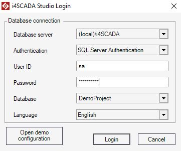
Select the [New Database] option from the Database drop-down list.
The New Database dialog is opened allowing the user to fill in the Database name.
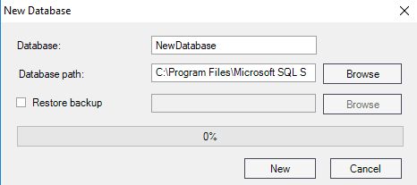
Press the button New to start generating the new Database.
Once the Database is prepared, press the Login button.
The i4scada Studio is opened. An information window pops-up asking the user to confirm if the new database should be set as Default or not.
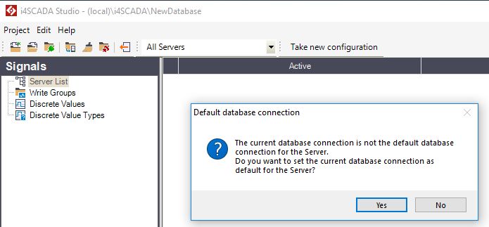
For the current use case, we shall set the New database as default, hence the button Yes should be selected.
Under the Signals section click right on the Server List node.
The Server contextual dialog is displayed. Select the option New Server.
A new Server node is added, under Server List. We shall name the new Server ".", as for the current use case the Server runs on the same machine as the i4scada Studio.
Select the Server node and click-right. Select the option New Connector / SNMP Connector from the contextual menu.
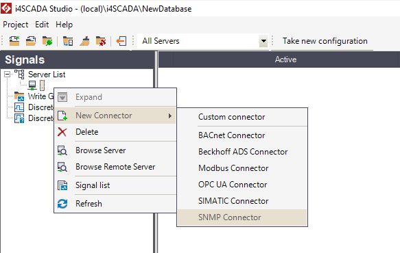
The SNMP Connector node is added to the hierarchical view.
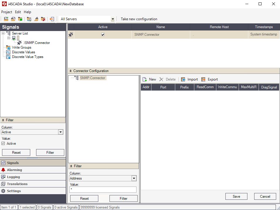
Further configuration steps, will be organized in the Connector Configuration panel.
Click the toolbar button New to add a new SNMP connection machine.

The new connection will be available in the tree structure, and the connection properties will be displayed in the properties table. Here, organise the following settings:

Enter the target machine's IP address (obtained by running the ipconfig command in Command Prompt) in the Address field. For tutorial purposes, enter your machine's own IP.
Enter a prefix in the Prefix field. For this example, enter My as a prefix.
Enter the ReadCommunity and the WriteCommunity as configured in the SNMP Service. In our Setting up the SNMP tutorial, the ReadCommunity was set up with the name readonly).
Press Save to save these settings.
Note
Now the new connection from the SNMP Connector is targeting the local machine.
Next, we will create a data output connection by selecting the machine connection defined earlier and clicking the New button from the toolbar.

The new data output will be available in the tree structure and the properties will be displayed in the properties table. Here, organise the following settings:

Enter the name of the data output in the Name field. For this example, we will use Processes, as the device in our case is the number of processes.
Enter the OID number in the OID field. For tutorial purpose, we will use the 1.3.6.1.2.1.25.1.6.0 OID number, which refers to the number of current running processes.
In order to be able to display the data from the targeted data output, select a syntax option from the Syntax menu. In this example, the correct syntax for displaying the number of current running processes is SNMP GAUGE32.
Leave the Writeable check-box unmarked, as the number of processes cannot be written, but only read.
For the Period property, leave the value at 1000 milliseconds.
Click Save to save the current changes.
Tip
In order to proceed with setting up the Signal for the SNMP Connector, please also refer to the upcoming tutorial.
Setting up the Signal for the SNMP Connector
In order to create a new signal in the SNMP.Connector, we need to create first a new signal group in our connector. Check out this tutorial to learn more.
Now the SNMP Connector is configured and connected to a data output. In order to see the actual data output, we need to create a signal for our data output. In order to create a new signal in the i4scada SNMP Connector, we need to create first a new signal group in our connector.
Note
Currently, i4scada only supports V1 and V2 of the SNMP protocol. V3 is not supported yet.
Select the connector from the Signals tab / Server List / Server and right-click in the empty pane from the right side. Select New Group.
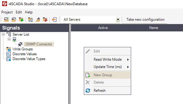
Now select the new group Group1 from the Signal tab / Server List / Server i4scada SNMP Connector and right-click in the right panel to create a new signal.
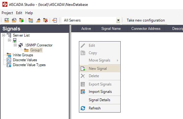
In the Signal Details panel, organize the following settings:
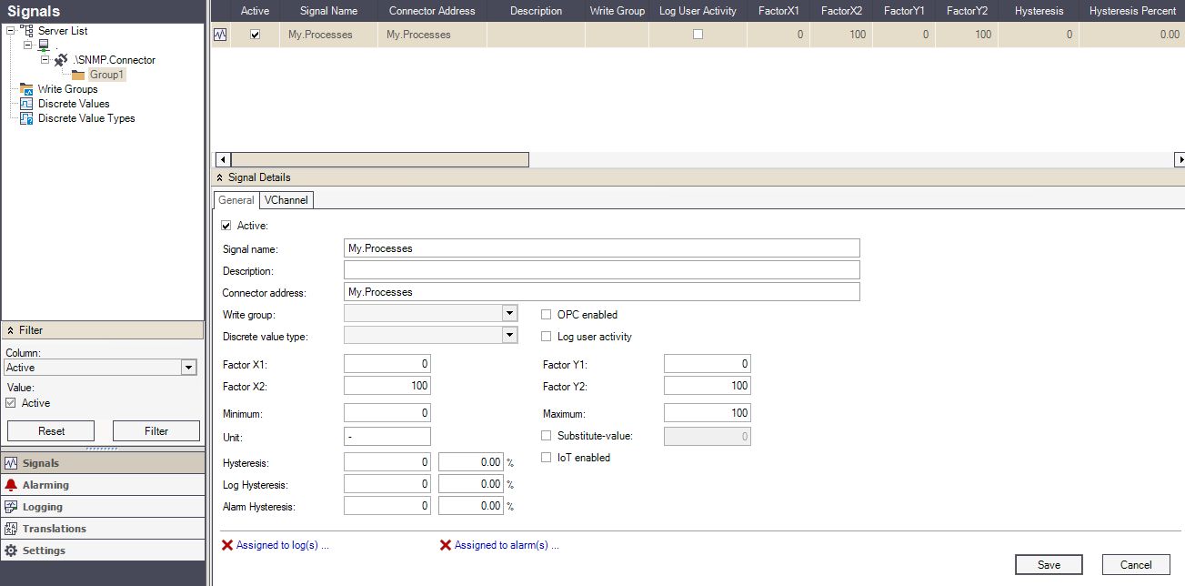
Name the signal as My.Processes.
Set the Connector address name to My.Processes too.
Press the button Save to preserve your changes.
Testing the My.Processes Signal and the SNMP Connector
Now for the final step in the SNMP Connector configuration tutorials, we shall test the new created Signal and the SNMP Connector.
To test the result of the previous tutorials, start the i4scada Server or restart it if it was running.
Open the i4scada Test Center application and import the My.Processes signal by clicking on Browse server from the top bar.

Select Group1 from the i4scada SNMP.Connector and select the My.Processes signal.
Click Import to import it, and Close to close the Browse Server window.

The Test Center should display the right value for the signal. To test the signal against the system, open the Windows Task Manager and check the number of running processes. It will be the same as the one displayed by the My.Processes signal in Test Center.
