Set Up Signals for the Connector
Check out this article to learn more details on how to configure and customise your i4scada Signals in just a few easy steps!
After defining the connector, you can set up the connector signals inside Studio using the Connector view. This view is active when a connector node is selected in the tree menu. The Connectors view displays the signal groups containing the available signals for the selected connector. The Connector view is identical for all the connectors available in Ewon by HMS Networks Studio.
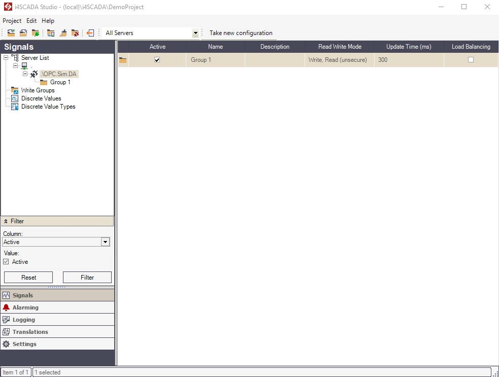
Studio mail view - Connector
When opening the Connector view for the first time, no signal group will be listed. The signal groups can be either created manually here or can be created automatically when importing connector signals. The following signal group properties are listed in the Connector view:
Active - if the Active check-box is marked, the signal group is taken into account when the i4scada Server is started.
Name - signal group name.
Description - optional description.
Read Write Mode - read/write permissions, applied to all the signals inside the group. Can be:
Read - the group's signals can only be read
Write - the group's signals can only be updated with new values, requiring a user with the appropriate rights.
Write, Read - the group's signals can be read and updated with new values, requiring a user with the appropriate rights.
Write (unsecure) - the group's signals can only be updated with new values, without requiring a user login
Write, Read (unsecure) - the group's signals can be read and updated with new values, , without requiring a user login
Update Time (ms) - the time interval for updating the signals data.
Load Balancing - if activated, the system will process only signals which are used in visualizations or in alarm conditions. If disabled, all available signals will be processed.
In order to be able to write signal values, a registered user must have access to the appropriate write group.
The signals can be defined in multiple ways: by browsing the available signals in the connector, by defining new signals inside the signal group or by importing saved signals inside the signal group.
Any defined signal is visible in the signals view. This view displays all the available signal information inside its grid. The same signal information is available for editing in the
Browsing the Connector
Right-click on the connector node in the tree menu and select Browse Connector. The Browse Connector dialog allows the user to select one or more available signals for the current connector and import them in the Ewon by HMS Networks Studio and place them into the selected signal group.
Select the desired signals and the destination signal group. If no signal group is defined, you can create a new one by typing the name of the new signal group directly into the Destination group field.
Click Add once the signals and destination signal group are selected. The signals will be imported in i4scada Studio.
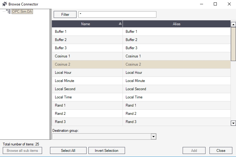
Browser Connector
Defining New Signals
To create new signals inside i4scada Studio, navigate to the signals view by selecting the signal group node in the tree menu.
Right-click either on the signal group node or the signals view and select New Signal.
A new signal will be added to the selected signal group. The signal properties can be set using the Signals Details panel at the bottom of the signals view.
Importing Saved Signals
To import saved signals in i4scada Studio, right-click either on the signal group node or in the signals view and select Import Signals.
Select the XML file containing the saved signals and click Open. The signals will be imported in the selected signal group, with the same settings as they were when exported.
Connector View Actions and Options
This section of the topic describes the actions that can be performed in the Connector view.
Tree menu contextual menu
Right-clicking on a Connector in the Signals tree menu will open the contextual menu. The Connector contextual menu provides options such adding or deleting signal groups, browsing the connectors for signals or validating signals.
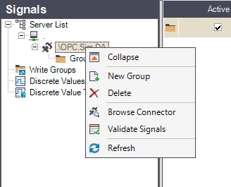
Connector contextual menu
Contextual menu of Connector node | Description |
|---|---|
Expand / Collapse | Expands / Collapses the Server view menu item, hiding or displaying the available connectors. |
New Group | Allows the user to add a new signal group to the connector. |
Delete | Deletes the selected connector. NoteConnectors having an understructure can not be deleted. Studio opens a dialog, providing more details concerning the reason why the selected connector cannot be deleted. 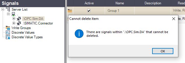 |
Browse Connector | Opens the Browse Connector dialog, allowing the user to add the signals available to the connector to the Studio project. |
Validate Signals | Opens the Validate Signals dialog, allowing the user to view the invalid or unused signals. |
Refresh | Reloads the list of connectors. |
Main panel contextual menu
Right-clicking on the signal groups listed in the main panel while a connector is selected will open the contextual menu. The contextual menu allows the user to edit the cell from where the contextual menu was opened, set the read/write mode for the signal group, and set the update time for the signal group. It also allows the user to create a new signal group, delete the selected one, and refresh the list.
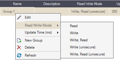
Signal Groups Read Write Mode contextual menu
Main panel contextual menu | Description |
|---|---|
Edit (context sensitive) | Edit the property from the currently selected grid cell. |
Read / Write Mode | Set read and write mode for the signal group. Can be:
|
Update Time (ms) | Select the time interval for process data transmission (50 - 60000 ms). |
New Group | Create a new signal group. |
Delete | Delete a signal group. 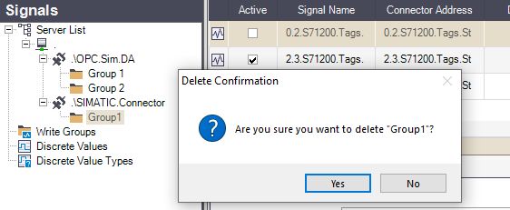 NoteSome Signal groups can not be deleted. Studio opens a dialog, providing more details concerning the reason why the selected signal group cannot be deleted. 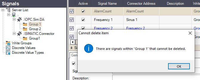 |
Refresh | Update the current view. |
Important
The contextual menu of the SIMATIC connector in the Signals tree menu provides different options! The Device number and the PLC number are crucial in defining the SIMATIC Connector's signals, inside Studio!
Also, the SIMATIC Connector configuration may be copied from one Server to another. To organize this action, copy all files from %ProgramData%\WEBfactory\SimaticConnector from the source server to the destination server.
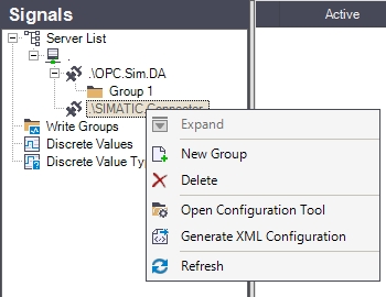
SIMATIC connector contextual menu
Contextual menu of the SIMATIC Connector node | Description |
|---|---|
Expand / Collapse | Expands / Collapses the Server view menu item, hiding or displaying the available connectors |
New Group | Allows the user to add a new signal group to the connector |
Deletes | Deletes the selected connector |
Open Configuration Tool | Opens the SIMATIC connector configuration tool (ACCON-AGLink V4 Configuration). |
Generate XML Configuration | Generates an XML configuration based on the settings applied to the SIMATIC connector in Ewon by HMS Networks Studio. The XML configuration is saved in the database. The Ewon by HMS Networks Server passes the configuration from the database to the connector. When any change has been applied to the SIMATIC connector in Ewon by HMS Networks Studio, an exclamation mark icon is displayed on the SIMATIC connector in the Signals tree menu. This means that the XML configuration must be generated using the SIMATIC connector contextual menu!  The XML configuration must be generated each time a setting is changed in Studio for the SIMATIC connector! |
Refresh | Reloads the list of connectors. |
Further on, to set up Signals inside Ewon by HMS NetworksStudio for the SIMATIC Connector, a special format must be used, in the Signal's Connector address. The Signal's connector address is composed of three import data:
the Device number - the Device number from the SIMATIC Connector's configuration tool
the PLC number - the PLC number from the SIMATIC Connector's configuration tool
the data type - see the data types list here.
The signal's connector address will look like this:
"Device_number"."PLC_number"/"data_type"
"Device_number"."PLC_number"\"data_type"
Note that the separator used between the Device_number and the PLC_number will always be "." (dot), while the separator used between the PLC_number and the data_type can be either "\" (back-slash) or "/" (forward-slash).
The following signals will be ignored (a message will be logged in the Activity Analyzer):
virtual signals (VChannel)
duplicate signals having the same Connector address
signals with an invalid format
Signals View Actions and Options
This section of the topic describes the actions that can be performed in the Signals view.
Tree menu contextual menu
Right-clicking on a Signal Group in the Signals tree menu will open the contextual menu. The Group contextual menu provides options such as adding or deleting signals, browsing the connectors for signals or exporting and importing signals.
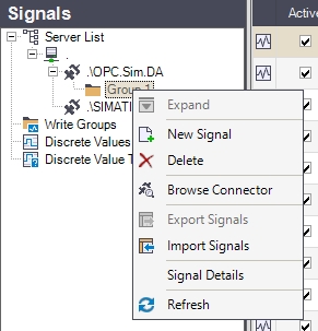
Signal Group contextual menu
Contextual menu of the Signal Group node | Description |
|---|---|
Expand / Collapse | Expand / Collapses the clicked elements. In the Group's case, the option is disabled because the Group cannot have any sub-items. |
New Signal | Allows the user to add a new signal to the signal group. |
Delete | Deletes the selected signal group.  NoteSome Signal groups can not be deleted. Studio opens a dialog, providing more details concerning the reason why the selected signal group cannot be deleted.  |
Browse Connector | Opens the Browse Connector dialog, allowing the user to add the signals available to the connector to the Studio project. |
Export Signals | Allows the user to export the signals belonging the selected signal group to an XML file on the hard-drive. |
Import Signals | Import signals from an XML file to the selected signal group. TipFor a tutorial describing the Import signals functionality, for the SIMATIC Connector signals, please also visit the dedicated tutorial here. |
Signal Details | Toggles the Signal Details panel on or off. |
Refresh | Reloads the signal list. |
Main panel contextual menu
Right-clicking on a signal listed in the main panel while a signal group is selected will open the contextual menu. The contextual menu allows the user to edit the cell from where the contextual menu was opened, manipulate signals (copy, move), create and delete signals, and export or import signals.
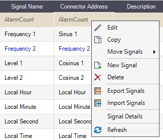
Listed Signal contextual menu
Contextual menu of Listed Signals | Description |
|---|---|
Edit | Edits the content of the cell where the contextual menu was triggered. |
Copy | Copies the selected signal(s) to clipboard, allowing the user to paste the clipboard content to another signal group. |
Move Signals | Allows the user to move the selected signal(s) to another group on the same connector or on a different connector. 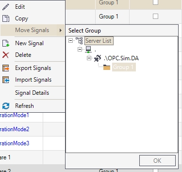 Move Signals |
New Signal | Allows the user to create a new signal. |
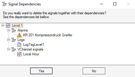
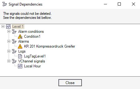
Delete | Deletes the selected signal(s). NoteOn attempt to delete a signal having dependencies, the Signal Dependencies dialog is opened, providing the user with more information about the type of dependencies:
TipOn an attempt to delete a signal, the system performs a check, looking for signal(s) associated dependencies (e.g. translations, alarm conditions, alarms, logs, etc.). Signals having alarm conditions or log conditions associated, cannot be deleted, until those dependencies are also removed. If there are other type of dependencies, the Signal Dependencies dialog will ask the user to confirm the deletion of the signal and all the corresponding dependencies. If the delete operation is finally approved, an attempt to delete the signal and all the corresponding dependencies is initiated. In case you encounter any issues, during the deletion operation, please also visit the dedicated troubleshooting article here. |
Export Signals | Allows the user to export the selected signal(s) to an XML file on the hard-drive. |
Import Signals | Imports signals from an XML file to the current signal group. TipFor a tutorial describing the Import signals functionality, for the SIMATIC Connector signals, please also visit the dedicated tutorial here. |
Signal Details | Toggles the Signal Details panel on or off. |
Refresh | Reloads the signal list. |
