Server's Connectors configuration
Everything that you need to know, to get acquainted with the i4scada Server's Connectors management, can be found in this article. Take a look!
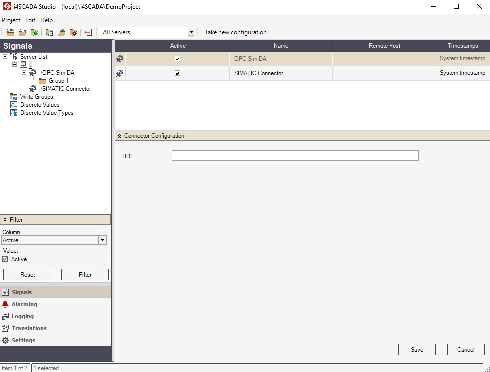
Once defined, a new server can be configured using the Server view. This view displays the list of connectors from the selected server and allows you to add, edit or remove connectors. When a native connector is selected, the Connector Configuration panel is available at the bottom of the main panel.
Server Connectors
Each connector defined for the selected server is listed in the view's grid, with the following properties:
Active - allows the user to activate or deactivate a connector.
Name - the name of the connector.
Remote Host - The name of the connector's host machine. The dot . represents the localhost.
Timestamps - that allows the user to select the desired timestamp:
System timestamp - the host’s system time as the timestamp
OPC timestamp - the connector’s system time as the timestamp
Optimized transmission - after a time cycle, an event is transmitted. Events within the cycle are not transmitted.
Secured transmission - each event is transmitted with the current timestamp.
There are multiple ways of configuring a new server: defining new connectors, browsing the server for existing services, or browsing remote servers for services.
Defining New Connectors
To add a new connector to a new server, right-click on the new server in the tree menu (or right-click in the empty space of the server view) and select New Connector.
Select one of the available connectors to be added to your server. Once added, the connectors can be configured either using the built-in Connector Configuration panel (only native connectors) or using the proprietary configuration methods. The available connectors are:
Custom Connector
BACnet Connector
Tip
Check a detailed description of the i4scada BACnet connector, here.
Beckhoff Connector
Tip
Check out our video tutorial explaining the usage of the Beckhoff ADS Connector in i4scada Studio.
Using the Beckhoff ADS Connector
Note
The Connector Configuration panel pops up when a native connector is selected. The Connector Configuration panel content varies depending on the selected connector.
The custom connectors (non-native connectors) have a different Connector Configuration panel that provides the option of connecting the connector to an OPC server using an URL.
Browsing the Server
Right-click on the server node in the tree menu and select the Browse Server option.
The Browse Server dialog will list the services available on the currently defined server. Select the required service and click Update. The appropriate connector will be added as a node under the server.
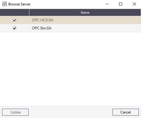
Browse Server
Browsing Remote Servers
Right-click on the server node in the tree menu and select Browse Remote Server.
The Entire Microsoft Network dialog allows you to browse the network and locate the machine running the server you need to connect to. Select the appropriate machine, and the Browse Server dialog will open, listing the services available on that machine.
Right-click on the server node in the tree menu and select Browse Remote Server.
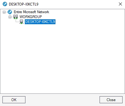
Browse Remote Server
Server View Actions and Options
This section of the topic describes the actions that can be performed in the current view.
Tree menu contextual menu
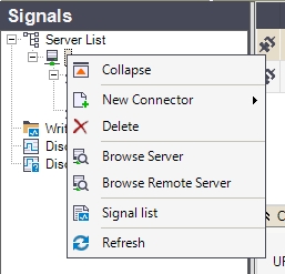
Right-clicking on the Server item in the Signals tree menu will open the contextual menu. The Server contextual menu provides options such as adding or deleting connectors, browsing the server for connectors, or refreshing the connectors list.
Connector contextual menu
Contextual menu of Connector node | Description |
|---|---|
Expand / Collapse | Expands/Collapses the Server view menu item, hiding or displaying the available connectors. |
New Connector | Allows the user to add one of the following connectors to the server:
|
Delete | Deletes the selected server. 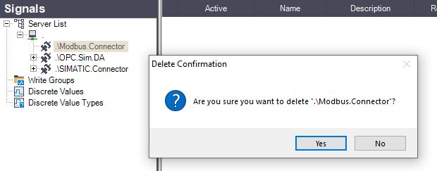 NoteConnectors having an understructure can not be deleted. Studio opens a dialog, providing more details concerning the reason why the selected connector cannot be deleted. 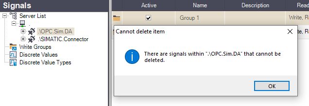 |
Browse Server | Opens the Browse Server dialog, allowing the user to add the connectors available on the local server to the Studio project. |
Browse Remote Serve | Opens the Browse Server dialog, allowing the user to add the connectors available on a remote server to the Studio project. |
Signal list | Opens the Signal Browser window, allowing the user to view the available signals for the selected server. |
Refresh | Reloads the list of servers. |
Main panel actions (contextual menu)
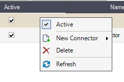
Right-clicking on a server listed in the main panel will open the contextual menu, providing the user with the options to edit the column in which the contextual menu is opened, add or delete servers, open the Signal Browser to view the signals from the selected server and refresh the server list.
Listed Server contextual menu
Contextual menu of Listed Server | Description |
|---|---|
Edit | Edits the cell in which the contextual menu has been opened (where the user right-clicked). |
New Connector | Allows the user to add one of the following connectors to the server:
|
Delete | Deletes the selected connector. NoteConnectors having an understructure can not be deleted. Studio opens a dialog, providing more details concerning the reason why the selected connector cannot be deleted. |
Refresh | Reloads the list of servers. |
i4scada Beckhoff ADS Connector
Learn more about the Beckhoff ADS Connector and the settings required to configure it on your i4scada machine, by reading this article.
The Beckhoff ADS Connector facilitates the communication between i4scada Studio and the devices which operate on the automation device specification interface, developed by Beckhoff.
Tip
For more details on how to use the Beckhoff ADS Connector in i4scada, please also visit our tutorials section.
Additionally, you can also check out the video tutorial on our YouTube channel.
i4scada Studio settings
Check out this article and learn how to configure the i4scada Studio settings in order to use the Beckhoff ADS Connector properly.
The Beckhoff ADS Connector Configuration panel allows the user to configure the devices using this connector and the signals associated with the devices.
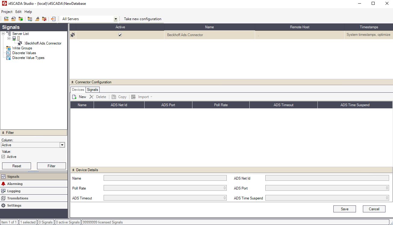
The i4scada Beckhoff ADS Connector
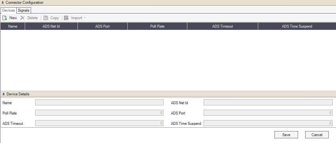
The Connector Configuration panel is split into two tabs: Devices and Signals.
The Devices section
The Devices tab allows the user with possibility manage up to 200 devices, linked in the ADS Network.
The Beckhoff ADS Devices TAB
The toolbar of the Devices tab features the following operations:

The Connector Configuration toolbar options
New - Adds a new device.
Delete - Deletes the selected device.
Copy - Copies the selected device one or more times. This is useful when having multiple devices in the same ADS network, using the same symbol lists.
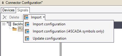
Import - Imports configurations:
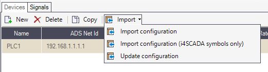
The Import options
Import configuration - imports a configuration from a TPY file.
Import configuration (i4scada symbols only) - imports i4scada symbols.
Update configuration - updates a configuration and allows the user to see the differences between the original configuration and the new one.
Once a new Device is added to the grid view the user can configure its parameters, as follows:

The Device parameters in grid view mode
Name - The unique name of the device. This serves as a device name for SignalPrefix.
ADS Net Id - The device address inside the ADS network.
ADS Port - The ADS communication port of the device.
Poll Rate - The time interval (in milliseconds) for polling the ADS device.
ADS Timeout - The timeout for communication operations (in milliseconds).
ADS Time Suspend - Suspend time after communication errors.
The same parameters are available for editing in the Device Details panel.
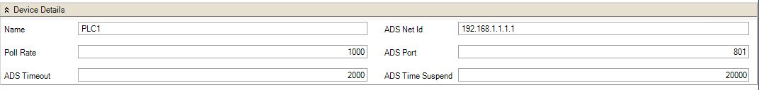
The Device parameters in detailed view mode
The Signals section
The Signals tab contains all the signals of the devices connected via the Beckhoff ADS Connector.
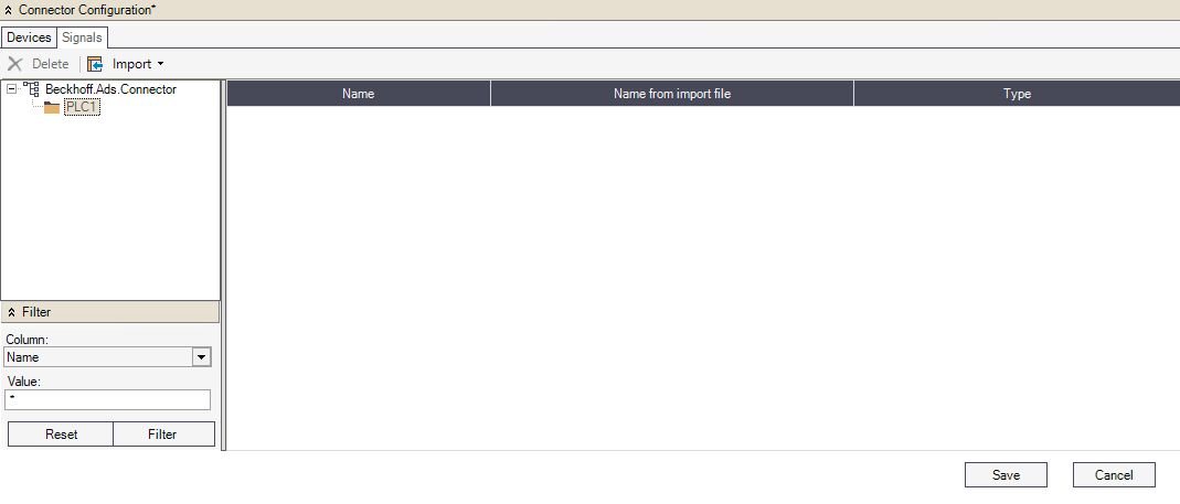
The i4scada ADS Signals TAB
The top menu allows the user to delete signals and import configurations from TPY files for the selected device.
The Import Signals options
Delete - Deletes the selected device.
Import - Imports configurations.
Import configuration - imports a configuration from a TPY file.
Import configuration (i4scada symbols only) - imports i4scada symbols.
Update configuration - updates a configuration and allows the user to see the differences between the original configuration and the new one.
The Signals panel tree menu allows the user to navigate between the connected devices and display the signals in the signals grid, individually, for each device.
The signals grid of the Connector Configuration panel displays the signals with their name, original name and type in the grid's columns. The available parameter columns are:
Name - The name of the signal in the project.
Name from import file - The original name of the signal in the TPY file.
Type - The type of the signal's value. Can be INT, REAL or STRING.
i4scada Modbus Connector
Learn more about the Modbus Connector and the settings required to configure it on your i4scada machine, by reading this article.
The Modbus Connector is integrated in i4scada being installed by default along with the i4scada Setup. The Modbus Connector does not have any additional system requirements, but in order to operate, a valid runtime license is needed.
Tip
For more details on how to use the Modbus Connector in i4scada, please also visit our tutorials section.
Additionally, you can also check out the video tutorial on our YouTube channel.
i4scada Studio Settings
Check out this article and learn how to configure the i4scada Studio settings in order to use the Modbus Connector properly.
The Modbus Connector Configuration panel allows the user to configure a Modbus communication link, set up a Modbus gateway and finally connecting the connector to a Modbus Device and its Signals.
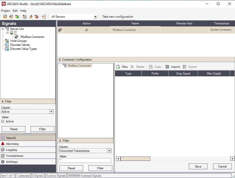
The i4scada empty Modbus Connector
The user can create new communication links, devices and signals in the Connector Configuration panel. In this view, the user can configure the devices and substations using this connector and the signals associated with the substations.
The toolbar for Modbus communication links provides the following operations:

New - Add a new Modbus cummunication link, gateway, Device or Signal.
Delete - Deletes the selected object.
Copy
Import - Imports a configuration from a Modbus configuration file.
Export - Exports a Modbus configuration file.
When adding a new device to the Modbus connector, the two options of connecting a device are displayed in the New dialog:
TCP - Modbus TCP (Transmission Control Protocol) is a communication protocol intended for supervision and control of automation equipment. Specifically, it covers the use of Modbus messaging in an 'Intranet' or 'Internet' environment using the TCP/IP protocols. Before adding the device, the user can configure the following settings:
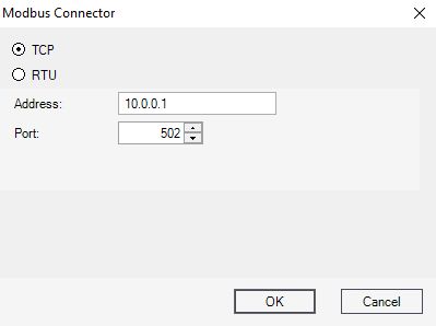
Modbus TCP device settings
Address - The IP address for the TCP connection.
Port - The port for the TCP connection.
RTU - Modbus RTU (Remote Terminal Unit) is an open serial protocol used within Building Management Systems (BMS) and Industrial Automation Systems (IAS). Before adding the device, the user can configure the following settings:
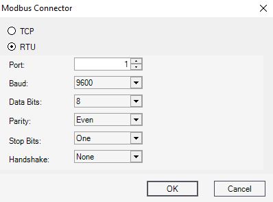
Modbus RTU Device settings
Port - The port for the RTU serial connection.
Baud - The rate of symbols changed per second.
Data Bits - The number of data bits in each character.
Parity - Parity bit used in detecting errors in transmission.
Stop Bits - The bits sent at the end of every character in order to allow the hardware to detect the end of a character.
Handshake - The flow control interaction.
Besides the above mentioned TCP and RTU settings, the user can configure the following Device specific settings:
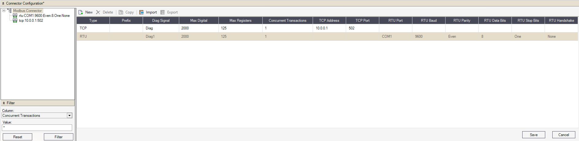
Modbus devices
Type - The type of connection for the device. Can be TCP or RTU.
Prefix - The prefix of the device.
Diag Signal - The Diagnose signal.
Max Digital - The maximum number of bit-sized digital data bits that would be placed in one packet. The highest value should be 2000.
Max Registers - The maximum number 16-bit register data that would be placed in one packet. The highest value should be 125.
Concurrent Transactions - The number of parallel gateway accesses made by the Modbus protocol. The gateway hosts several devices accessed by Modbus, devices that are distinguished based on their unit ID's.
By selecting a Modbus device in the hierarchical view, the user can organise the following operations, in order to manage Modbus device substations:
New - Adds a new Modbus device substation.
Delete - Removes the selected item.
Copy - Copies a Modbus device substation.
The Modbus device substations can be configured in the Connector Configurations grid-view, as follows:
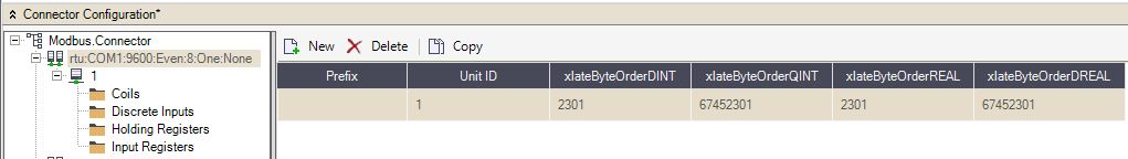
Substations grid view
Prefix - The prefix of the substation.
Unit ID - The ID of the Modbus device inside the Modbus network (substation).
xlateByteOrderDINT - The parameter used to set the bytes order for integer 32 bits values. The Modbus connector accepts four possible byte order values for 4 bytes data types:
0123
1032
2301
3210
The default byte order value is 2301.
xlateByteOrderQINT - The parameter used to set the bytes order for integer 64 bits values. The Modbus connector accepts four possible byte order values for 8 bytes data types:
01234567
03254766
17453201
76543210
The default byte order value is 67452301.
xlateByteOrderREAL - The parameter used to set the bytes order for floating point 32 bits values. The Modbus connector accepts four possible byte order values for 4 bytes data types:
0123
1032
2301
3210
The default byte order value is 2301.
xlateByteOrderDREAL - The parameter used to set the bytes order for floating point 64 bits values. The Modbus connector accepts four possible byte order values for 8 bytes data types:
01234567
10325476
67453201
76543210
The default byte order value is 67452301.
Further on, by selecting a Modbus substation, a set of Data Types will be displayed, as follows:
Data Type - The type of data represented by associated signals:
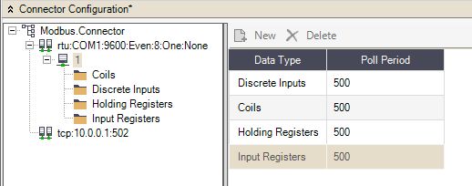
The Data Types view
Coils - On/off discrete values that can be read and written Bitwise (bit by bit)
Discrete Inputs - On/off discrete values that can be only read Bitwise (bit by bit)
Holding Registers - Numerical values that can be read and written Wordwise (word by word).
Input Registers - Numerical values that can be only read Wordwise (word by word).
Poll Period - The polling period of the available data type signals.
Each type of data can be defined as a signal. By selecting a Data Type from the hierarchical view, the toolbar will allow the user with the following operations:
New - Adds a new Signal for the selected Data Type.
Delete - Removes the selected item.
Copy - Copies a Modbus Signal.
Based on the originating Data Type, each Signal features the following properties:
Coils
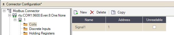
Properties of a Coil Signal
Name - The name of the signal.
Address - The address of the signal in the OPC server.
Unreadable - If enabled, this signal value will not be available in the server.
Discrete Inputs
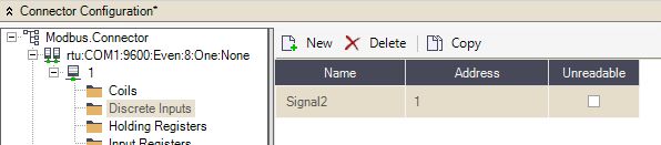
Properties of a Discrete Inputs Signal
Name - The name of the signal.
Address - The address of the signal in the OPC server.
Unreadable - If enabled, this signal value will not be available in the server.
Holding Registers
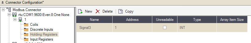
Properties of a Holding Registers Signal
Name - The name of the signal.
Address - The address of the signal in the OPC server.
Unreadable - If enabled, this signal value will not be available in the server.
Type - The type of data. The data type can be scalar or array.
Scalar data types:
INT - 16 bits signed integer
UINT - 16 bits unsigned integer
DINT - 32 bits signed integer
DUINT - 32 bits unsigned integer
QINT - 64 bits signed integer
QUINT - 64 bits unsigned integer
REAL - 32 bits float
DREAL - 64 bits float
Array data types, each one corresponding to the scalar data types:
INTARRAY
UINTARRAY
DINTARRAY
DUINTARRAY
QINTARRAY
QUINTARRAY
REALARRAY
DREALARRAY
Array Item Size - The size of the array, if the array data types are selected.
Input Registers
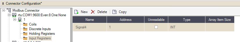
Properties of an Input Registers Signal
Name - The name of the signal.
Address - The address of the signal in the OPC server.
Unreadable - If enabled, this signal value will not be available in the server.
Type - The type of data. The data type can be scalar or array.
Scalar data types:
INT - 16 bits signed integer
UINT - 16 bits unsigned integer
DINT - 32 bits signed integer
DUINT - 32 bits unsigned integer
QINT - 64 bits signed integer
QUINT - 64 bits unsigned integer
REAL - 32 bits float
DREAL - 64 bits float
Array data types, each one corresponding to the scalar data types:
INTARRAY
UINTARRAY
DINTARRAY
DUINTARRAY
QINTARRAY
QUINTARRAY
REALARRAY
DREALARRAY
Array Item Size 0 The size of the array, if the array data types are selected.
i4scada OPC-UA Connector
Learn more about the OPC-UA Connector and the settings required to configure it on your i4scada machine.
The OPC-UA connector is a machine-to-machine communication protocol for industrial automation. As the i4scada OPC-UA Connector involves changes at the level of i4scada Studio, the scope of this article is to explain the configuration steps, as follows:
Tip
For a step-based tutorial, please also visit the i4scada OPC-UA Tutorials chapter.
Additionally, you can also check out the video tutorial on our YouTube channel.
i4scada Studio settings
Get started with the i4scada OPC-UA Connector configuration. Here are the Studio settings required to get it working!
When creating or adding a connector in i4scada, a certificate will be automatically saved in the local application folder, of the current user (e.g. C:\Users\[current_user]\AppData\Local\Webfactory).
An empty OPC-UA Connector configuration will look like this:
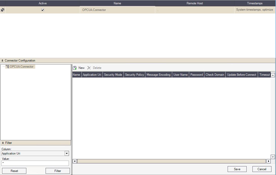
Empty OPC-UA Connector configuration
The OPC-UA Connector allows the user to configure the connector timestamps, selecting from the following options:
System timestamps, optimised update processing - the host’s system time, as optimised transmission.
System timestamps, secured update processing - the host’s system time, as secured transmission.
OPC timestamps. optimised update processing - the connector’s system time as optimised transmission. The optimised update processing, ensures that after a time cycle, an event is transmitted. Events within the cycle are not transmitted.
OPC timestamps, secured update processing - the connector’s system time as secured transmission. The secured update processing ensures that each event is transmitted with the current timestamp.
The structure of an i4scada OPC-UA Connector contains Sessions, Subscriptions, and Items .
OPC-UA Sessions
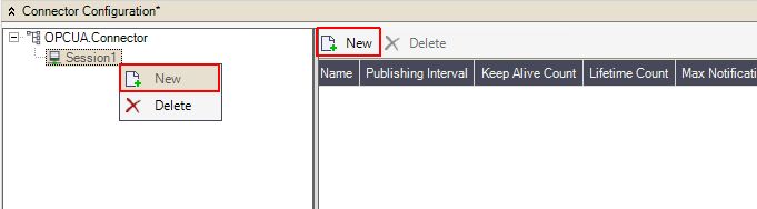
The user can assign to the i4scada OPC-UA Connector one or more sessions, in the Connector Configuration panel. The create function is provided by the button new, available either in the toolbar or by right-clicking on the OPC-UA Connector node.
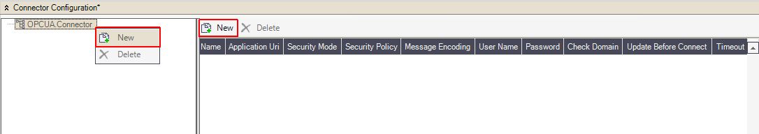
Create a new Session for the OPC-UA Connector
Clicking the button New opens the OPC-UA Connector window, where the user can start defining a new Session. In this view, the following options are featured:
Server Url field - allows the user to type in the Url to an OPC-UA Server.
Connect button - establishes the connection to the OPC-UA.
Trust server without certificate check-box - allows the user to create a new session for an endpoint without a certificate.
Endpoints grid-view - displays the list of OPC-UA Server endpoints.
Create button - selects the OPC-UA Server endpoints and adds them to the Sessions grid-view.
Remove button - deletes the sessions from the grid-view.
Sessions grid-view - displays the list of sessions that are ready for the import.
Import button - imports the created session(s) to the the OPC-UA Connector.
Close button - closes the OPC-UA Connector window, without preserving any changes.
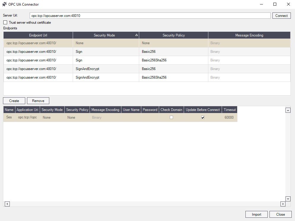
OPC-UA Connector window
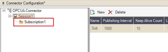
Once the newly created Session is imported to the OPC-UA Connector, a new node is added to the hierarchical view in the Connector Configuration panel.
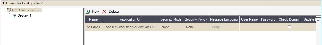
A New Session added to the hierarchy
Multiple Sessions can be added to the OPC-UA Connector by means of the option New.
Also, it is possible to remove Sessions, by means of the Delete option available in the toolbar, or accessible by right-clicking on the OPC-UA Connector node.
For a step-based tutorial on the creation of Sessions, please also visit the chapter Configuring the OPC-UA Connector in i4scada Studio.
OPC-UA Subscriptions
It is easy to manage OPC-UA Subscriptions once you find where to go. This article explains how to add new Subscriptions and how to manage them.
The OPC-UA Subscriptions are subordinated to Sessions, so in order to create them, the user can Select the option New, either in the toolbar or by right-clicking on the OPC-UA Connector node.
New Connector Configuration
Automatically, after clicking the option New, the Subscription is added to the hierarchical view of the OPC-UA Connector.
New Subscription added
In this view, the user can add one or more Subscriptions to OPC-UA Connector Sessions. The redundant Subscriptions can be removed by using the Delete option, available either in the toolbar, or by right-clicking on the Session node.
For a detailed description of how to add Subscriptions, please also visit the Tutorials chapter Configuring the OPC-UA Connector in i4scada Studio .
OPC-UA Items
The OPC-UA Items are the main elements of the i4scada OPC-UA Connector. Check out the list of OPC-UA Items supported value types and learn how to manage them.
While configuring the OPC-UA Connector, the user can assign Items to the created Subscriptions, by using the option New, available in the toolbar, or by right-clicking the Subscriptions node, in the hierarchical view.
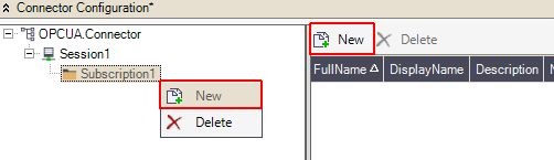
New Items
By clicking the option New, the Server nodes window pops-up, where the user can browse for monitored Items (OPC-UA variables) and select the desired Objects, from the hierarchical view. Once a set of Objects is selected or expanded, the grid-view is populated with all the node variables. The needed variables can be selected from the grid-view and imported to the OPC-UA Configurator, by means of Import or Import all options.
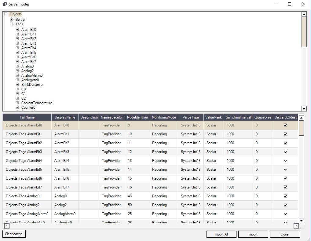
Server nodes window
The following Value types are supported by the WEBfactory i4scada OPC-UA Items:
Boolean
SByte
Byte
Int16
UInt16
UInt32
UInt32
Int64
UInt64
Single
Double
Decimal
DateTime
String
The Items having a value type different than the types listed above, the value type will not be recognized (NULL), and the Item will not be visible in the OPC-UA Items list.
Note
The user can define custom value types, for the OPC-UA Items, by defining mappings between the custom value type and the types listed above. The custom value type mappings with the WEBfactory i4scada OPC-UA value types can be organized in the Opc.Ua.CustomTypes.xml file.
This file is available in the i4scada Studio folder, through the path "C:\Program Files (x86)\i4scada\Studio".
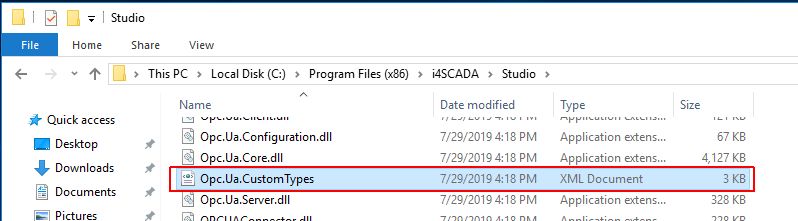
The Opc.Ua.CustomTypes.xml file
In the lower part of the Server nodes window, the user can click on the Clear caches button. If the Clear caches button is clicked, the internal cache is cleared and data is retrieved from the OPC-UA Server, instead.
To leave the Server nodes, the user can click on the Close button. The user can close the Server nodes window after importing the desired Items, or without making any changes in this view.
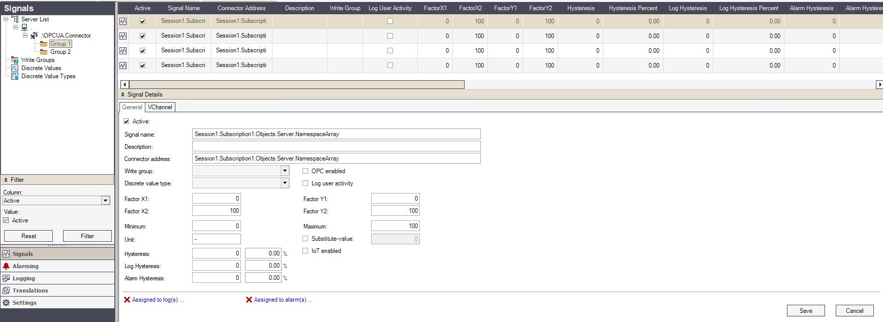
After importing Items to the OPC-UA Connector Subscription, the grid-view under the Connector Configuration panel is populated with data. Some of the fields of these grid-views, can be edited, by clicking directly in the field cell.
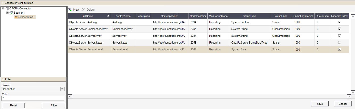
Subscription Items
For a detailed description of the necessary steps to add Items to Subscriptions, please also visit our tutorials chapter Configuring the OPC-UA Connector in i4scada Studio.
Signal mappings
Map your OPC-UA Items with i4scada Signals in order to populate your OPC-UA Connector with fully customizable Signals.
After the OPC-UA Connector has been defined and it has at least one Session, one Subscription, and one Item, the user can proceed and map the Subscription Items (OPC-UA variables) into WEBfactory Signals.
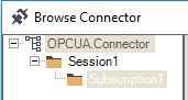
By right-clicking on the OPCUA Connector in the Signals panel of i4scada Studio, the option Browse Connector is available.
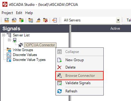
Browse Connector
The Browse Connector window allows the user to add one or more available variables and map them to WEBfactory Signals. In this view, the user can also create a new Signal Group, by typing the name of it, directly in the Destination group field.
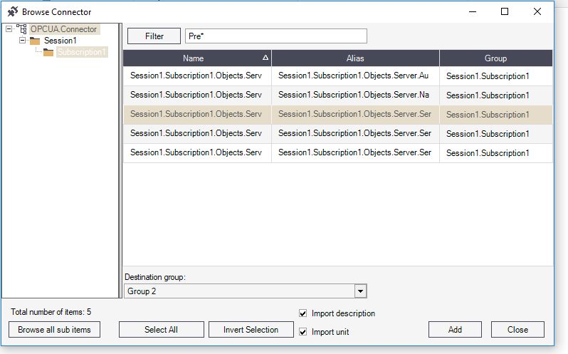
Browse Connector window
In the Browse Connector window, the following panels and options are featured:
The Hierarchical view - displays the OPC-UA Connector and its structure.
The Filter panel - The filter panel allows the user to filter the available signals using the values of the Name column (of the main view grid) in combination with wildcards.

The Main view - The main view of the Browse Connector window, displays the list of available variables and allows the user to select items for importing. This list allows single and multi-selection, as well.
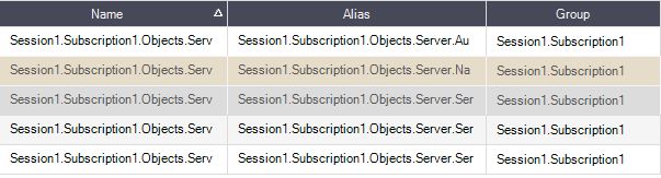
Destination group - The Destination group drop-down list allows the user to select the Signal group in which to map the selected variables into signals.
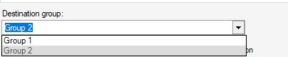
It also allows the user to create a new Signal group, by simply typing the name of it in the text area. The Signal group will be created and the selected signals will be automatically added to it when the Add button is pressed.
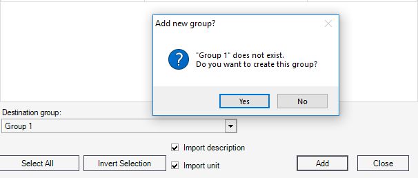
Additional functionality - The Browse Connector dialog allows the user to quickly browse all the connector items, select all available variables from the main view, and invert the current selection. Also, the user is able to import the variable description.
Browse all sub items button - Automatically displays all the available variables/signals and the groups to which they belong, in the main view.
Select All button - Selects all the signals available in the main view.
Invert Selection button - Inverts the current selection.
Import description check-box - If enabled, imports the Description of variables/signals, as well.
Import unit check-box - If enabled, imports the Unit of variables/signals unit, as well.
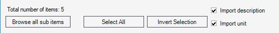
Add button - imports the selected variable/signal, to the Signal Group
Close button - closes the Browse Connector window.
After selecting the variables, from the Browse Connector window, selecting a Signal Group, and clicking the Add button, the system maps the variables to WEBfactory Signals. The Group(s) of OPC-UA Connector are populated with Signals that can be customized as desired.
OPC-UA Signals
i4scada SIMATIC Connector Configuration
Add to your i4scada Studio Project a SIMATIC Connector and establish communication with all S7 PLC series, using the S7-TCP/IP and S7 TCP/IP channels.
The i4scada SIMATIC Connector allows the user to establish communication with all the S7 PLC series, using the S7-TCP/IP and S7-TCP/IP TIA channels.
In the i4scada Studio, the SIMATIC Connector can be added in the project using the contextual menu of the server from the Signals tree menu.
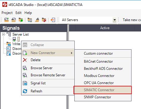
Add a SIMATIC Connector
Tip
For a step-based tutorial, please also visit the articles in the i4scada SIMATIC Connector Tutorials section.
Additionally, you can also check out the video tutorial on our YouTube channel.
Supported Data Types
The following table contains all the supported data types:
Description | Format | Range | Example | Data Type |
|---|---|---|---|---|
Input bit | Ix.y | x:0-65535 y:0-7 | I2.0 | bool |
Input byte / unsigned | IBx | x:0-65535 | IB4 | byte |
Input word / unsigned | IWx | x:0-65534 | IW0 | ushort |
Input word / signed | IWx:INT | x:0-65534 | IW6:INT | short |
Input double word / unsigned | IDx | x:0-65532 | ID4 | uint |
Input double word / signed | IDx:DINT | x:0-65532 | ID4:DINT | int |
Input double word / REAL | IDx:REAL | x:0-65532 | ID4:REAL | float |
Output bit | Qx.y | x:0-65535 y:0-7 | Q2.0 | bool |
Output byte /unsigned | QBx | x:0-65535 | QB4 | byte |
Output word / unsigned | QWx | x:0-65534 | QW0 | ushort |
Output word / signed | QWx:INT | x:0-65534 | QW6:INT | short |
Output double word / unsigned | QDx | x:0-65532 | QD4 | uint |
Output double word / signed | QDx:DINT | x:0-65532 | QD4:DINT | int |
Output double word / REAL | QDx:REAL | x:0-65532 | QD4:REAL | float |
Marker bit | Mx.y | x:0-65535 y:0-7 | M2.0 | bool |
Marker byte / unsigned | MBx | x:0-65535 | MB4 | byte |
Marker word / unsigned | MWx | x:0-65534 | MW0 | ushort |
Marker word / signed | MWx:INT | x:0-65534 | MW6:INT | short |
Marker double word / unsigned | MDx | X:0-65534 | MD4 | uint |
Marker double word / signed | MDx:DINT | x:0-65532 | MD4:DINT | int |
Marker double word / REAL | MDx:REAL | x:0-65532 | MD4:REAL | float |
Time / S5Time | Tx | x:0-? | T0 | string |
Time / BCD | Tx:BCD | x:0-? | T0:BCD | ushort |
Counter / BCD | Cx | x:0-? | C0 | short |
Counter / word | Cx:WORD | x:0-? | C0:WORD | ushort |
Data bit | DBz.DBXx.y | x:0-65535 y:0-7 z:1-65536 | DB54.DBX1.0 | bool |
Data bit - array | DBz.DBXx.y[0..w] | x:0-65535 y:0-7 z:1-65536 w:0-? | DB54.DBX1.0[0..2] | bool[] |
Data byte / unsigned | DBz.DBBx | x:0-65535 z:1-65536 | DB63.DBB12 | byte |
Data byte - array | DBz.DBBx[0..w] | x:0-65535 w:0-(65535 - x) z:1-65536 | DB63.DBB12[0..5] | byte[] |
Data byte / ASCII - array | DBz.DBBx:ASCII[0..w] | x:0-65535 w:0-(65535 - x) z:1-65536 | DB50.DBB0:ASCII[0..4] | string |
Data byte / signed | DBz.DBBx:CHAR | x:0-65535 z:1-65536 | DB63.DBB12:CHAR | char |
Data byte / signed - array | DBz.DBBx:CHAR[0..w] | x:0-65535 w:0-(65535 - x) z:1-65536 | DB63.DBB12:CHAR[0..5] | char[] |
Data byte / STRING | DBz.DBBx:STRING | x:0-65533 z:1-65536 | DB50.DBB0:STRING | string |
Data word / unsigned | DBz.DBWx | x:0-65534 z:1-65536 | DB10.DBW292 | ushort |
Data word / unsigned - array | DBz.DBWx[0..w] | x:0-65534 w:0-((65536 – x) / 2) - 1) ; rounded down z:1-65536 | DB10.DBW292[0..7] | ushort[] |
Data word / signed | DBz.DBWx:INT | x:0-65534 z:1-65536 | DB10.DBW292:INT | short |
Data word / signed - array | DBz.DBWx:INT[0..w] | x:0-65534 w:0 - ((65536 – x) / 2) - 1) ; rounded down z:1-65536 | DB10.DBW292:INT[0..7] | short[] |
Data word / S5Time | DBz.DBWx:S5TIME | x:0-65534 z:1-65536 | DB10.DBW292:S5TIME | string |
Data word / DATE | DBz.DBWx:DATE | x:0-65534 z:1-65536 | DB10.DBW294:DATE | string |
Data double word / unsigned | DBz.DBDx | x:0-65532 z:1-65536 | DB10.DBD24 | uint |
Data double word / unsigned – array | DBz.DBDx[0..w] | x:0-65532 w:0 - ((65536 – x) / 4) - 1) ; rounded down z:1-65536 | DB10.DBD24[0..8] | uint[] |
Data double word / signed | DBz.DBDx:DINT | x:0-65532 z:1-65536 | DB10.DBD24:DINT | int |
Data double word / signed – array | DBz.DBDx:DINT[0..w] | x:0-65532 w:0 - ((65536 – x) / 4) - 1) ; rounded down z:1-65536 | DB10.DBD24:DINT[0..8] | int[] |
Data double word / REAL | DBz.DBDx:REAL | x:0-65532 z:1-65536 | DB10.DBD24:REAL | float |
Data double word / REAL - array | DBz.DBDx:REAL[0..w] | x:0-65532 w:0 - ((65536 – x) / 4) - 1) ; rounded down z:1-65536 | DB10.DBD24:REAL[0..8] | float[] |
Data double word / TIME | DBz.DBDx:TIME | x:0-65532 z:1-65536 | DB10.DBD24:TIME | string |
Data double word / TIME_OF_DAY | DBz.DBDx:TIME_OF_DAY | x:0-65532 z:1-65536 | DB10.DBD24:TIME_OF_DAY | string |
DATE_AND_TIME | DBz.DBBx:DATE_AND_TIME | x:0-65528 z:1-65536 | DB10.DBB300:DATE_AND_TIME | string |
Supported PLCs and TIA Versions
Check out these tables to learn which PLC types and TIA versions are supported by the i4scada OPC-UA Connector.
The below table reflects the list of supported PLC types:
PLC Type | Firmware | Read symbol information from the TIA Project Portal | Online symbolic access * | Online absolute access via PUT/GET ** |
|---|---|---|---|---|
S7-300 | All | Yes | No | Yes |
S7-400 | All | Yes | No | Yes |
S7-1200 | 2.2. up to 4.4 | Yes | Yes | Yes (not recommended) |
S7-1500 | 1.0 up to 2.8.3 | Yes | Yes | Yes (not recommended) |
* Functions: AGL_Symbolic_ReadMixEx(), AGL_Symbolic_WriteMicEx()
** Functions: AGL_ReadMixEx(), AGL_WriteMixEx()
Currently, the following TIA versions are supported:
TIA Version | Service Pack |
|---|---|
11 | up to Service Pack 2 (Update 5) * |
12 | up to Service Pack 1 (Update 4) * |
13 | up to Service Pack 2 * |
14 | up to Service Pack 1 |
15 | |
16 |
*: No further changes will be organized, for the TIA Portal project formats V11, V12 and V13. The formats are still usable.
i4scada Studio settings
Check out this article for a better understanding of the i4scada SIMATIC Connector contextual menu options.
Unlike the other connectors available in the i4scada Studio, the SIMATIC Connector offers a slightly different functionality.
Besides the already familiar options of creating signal groups, deleting the connector, or refreshing the list, the SIMATIC Connector contextual menu, offers the following particular options:
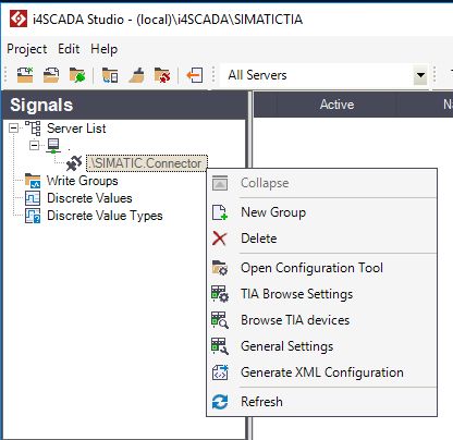
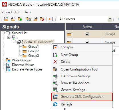
Contextual menu of the SIMATIC Connector
Open configuration tool - Opens the SIMATIC connector configuration tool (ACCON-AGLink V4 Configuration) where the user can configure devices of type S7-TCP/IP and S7-TCP/IP TIA.
TIA Browse settings - Opens a window where the user can browse TIA settings. The window will only be opened, if a device of type S7-TCP/IP TIA has been previously configured. At this step, the user can select the browse type of the device to be either PLC, PLC Project, or PLC Binary.
Tip
For faster and more reliable communication, the user is advised to use the PLC Binary Browse type, for TIA devices.
Browse TIA devices - Opens the list of all S7-TCP/IP TIA devices, PLCs, symbols, blocks and tags. The window will only be opened, if a device of type S7-TCP/IP TIA has been previously configured. At this step, the user can import TIA symbols, that will be mapped into Ewon by HMS Networksi4scada Signals.
General Settings - Opens the General Settings window, where all the configured devices, regardless of their type, are listed.
Generate XML Configuration - Generates an XML configuration based on the settings applied to the SIMATIC connector in i4scadaStudio.
IMPORTANT
The user must Generate XML Configuration whenever the SIMATIC connector configuration has been changed!
Open Configuration Tool
The Configuration Tool allows the user with possibility to configure SIMATIC devices of type S7-TCP/IP and S7-TCP/IP TIA.
The SIMATIC Connector contextual menu Open Configuration Tool allows the user to configure SIMATIC devices of type S7-TCP/IP and S7-TCP/IP TIA.
The changes organized in the ACCON-AGLink V4 Configuration window can be saved by clicking the button Apply, followed by the button OK.
The ACCON-AGLink V4 Configuration window features three tabs:
The Configuration Tool - ACCON-AGLink V4 Configuration window
The Devices tab
Under the Devices tab, the user can add multiple devices of type S7-TCP/IP and S7-TCP/IP TIA.
The Devices tab
The view is split up into two panels:
The list of devices panel
The configuration panel
TCP/IP or TCP/IP TIA tab
Connections tab
The list displays a set of 16 devices, however, the amount of displayed devices can be changed under Options Program tab, as described below. To configure the list of devices, the user can select the desired option from the drop-down lists, as follows:
Device of type S7-TCP/IP.
Device of type S7-TCP/IP TIA.
Not active (set by default). Having this option set, no further configuration settings are available.
Not supported. Having this option set, no further configuration settings are available.
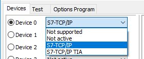
Selector of device type
The view under the configuration panel is structured on two tabs: the device configuration and the device connection settings. The settings under these two tabs differ on the basis of the user selection, organized in the list of devices.
Hence, we can either have the configuration panel of S7-TCP/IP device or the configuration panel of S7-TCP/IP TIA device.
Under the Connections tab, the user is provided with the following general settings:
Change... - opens the Connection edit dialog. Alternatively, the user can double-click the device row, that needs to be added/updated.
Delete - deletes the selected device row.
Adjust columns - adjust the columns' width, to fit the text.
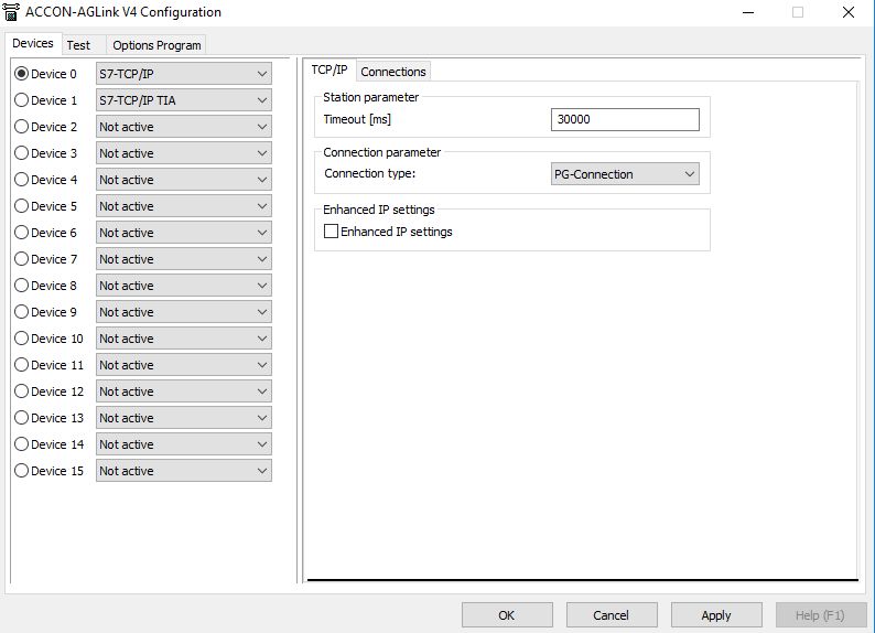
Configuration panel of S7-TCP/IP device
When adding an S7-TCP/IP device, the TCP/IP configuration panel features the following settings:
Station parameter
Timeout [ms] - specifies the time that the PLC will wait for a response from the device before giving up and going on to the next request. The timeout range is expressed in milliseconds. By default the value is set to 30000 milliseconds.
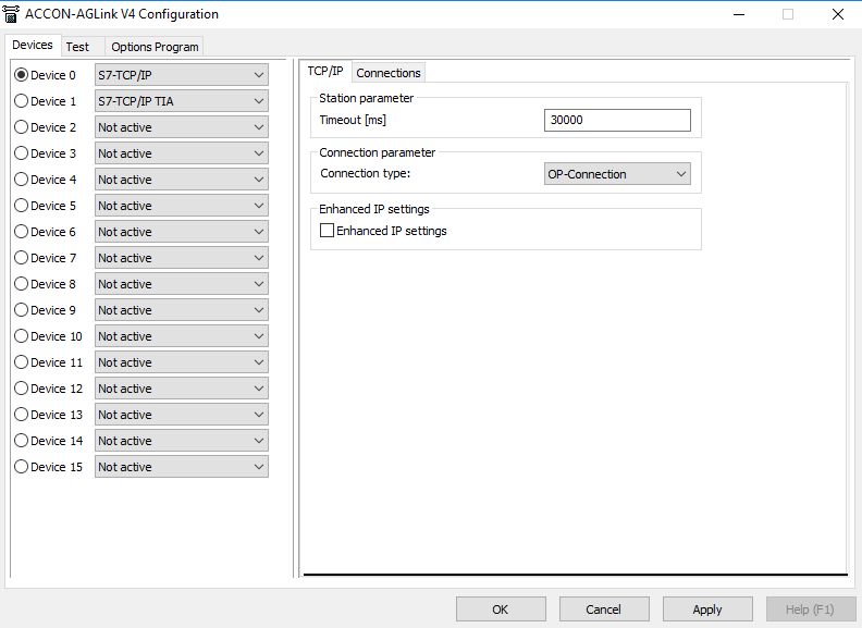
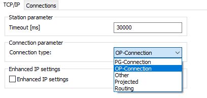
Connection parameter
Connection type - specifies the type of device connection, allowing the user to select between:
PG-Connection - communication service supporting the protocol that S7 controllers use to communicate with various programming devices.
OP-Connection - communication service supporting the protocol that S7 controllers use to communicate with various HMI devices.
Other - other modules with communication functionality.
Projected - communication type that can establish connections between multiple PLCs. With projected connections, it is not possible to communicate over un-projected connections.
Routing - communication type that can access devices across sub-net boundaries.
The selection of connection type is organized from a drop-down list. The selection is by default set to value OP-Connection.
Enhanced IP settings check-box - if enabled, the network services are set to the enhanced Internet Protocol and use enhanced mode capabilities. Under the Connections tab, the user will be allowed to fill in two additional fields: Port and Local IP Address.
TCP/IP tab
Once the devices have been set up, the user has the ability to connect different PLCs to the S7-TCP/IP devices. These settings can be processed under the Connections tab.
Both the header and the available settings under the Connections tab can change, depending on the Connection type selected under the TCP/IP tab, as follows:
Connections tab - for PG-Connection, OP-Connection and Other.
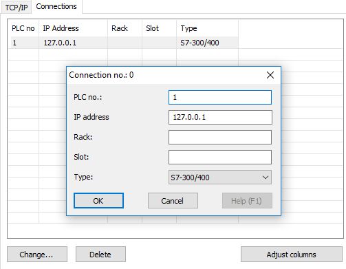
The TCP/IP Connections tab
When connecting a PLC to the S7-TCP/IP device, the user must specify the PLC allocated number, the IP address, the Rack, the Slot and the Type. The PLC types that can communicate with the S7-TCP/IP device are:
S7-300/400 - used for larger tasks such as the coordination of entire systems.
S7-200 - used in the micro automation area, with a broad scale of modules.
S7-1200/1500 - used to perform automation tasks in the lower to medium performance range (S7-1200) up to maximum performance and the shortest reaction times (S7-1500).
LOGO! - used for small automation projects, such as home automation.
Proj. Connections tab - for Projected Connection.
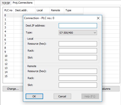
The TCP/IP Proj. Connections tab
When connecting a PLC to the S7-TCP/IP device, with a projected communication, the user must specify the Destination IP Address, the PLC type, the Resource (hex), the Rack, the Slot for both Local and Remote resources.
Routing tab - for Routing Connection.
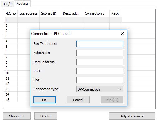
The TCP/IP Routing tab
When connecting a PLC to the S7-TCP/IP device, via routing communication, the user must specify the Bus IP Address, the Subnet-ID, the Destination address, the Rack, the Slot and the Connection type (available selections being PG-Connection, OP-Connection and Other).
Configuration panel of S7-TCP/IP TIA device
The Totally Integrated Automation (TIA) devices provide access to a wide range of digitized automation services. When adding and configuring an S7-TCP/IP TIA device, the steps are similar to the S7-TCP/IP device.
In the configuration panel, the user can organize the following settings:
Station parameter
Timeout [ms] - specifies the time that the PLC will wait for a response from the device before giving up and going on to the next request. The timeout range is expressed in milliseconds. By default the value is set to 30000 milliseconds.
Connection parameter
Connection type - specifies the type of device connection, allowing the user to select between HMI, ES, DL and Other. The default connection type is set to HMI.
Enhanced IP settings check-box - if enabled, the network services are set to the enhanced Internet Protocol and use enhanced mode capabilities. Under the Connections tab, the user will be allowed to fill in two additional fields: Port and Local IP Address.
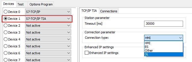
Configuration panel of S7-TCP/IP TIA device
After the TIA device has been configured, the user can proceed with the connections configurations, that are the same, regardless of the selected connection type.
PLC no - the number allocated to the PLC device
IP Address - the IP Address of the PLC to which the device should connect
Type - the PLC type
Auto Detect - automatically detects the PLC from a list of available devices on the network.
S7-1200 TIA - used for compact automation solutions with integrated communication and technology functions.
S7-1200 TIA FW>=4 - S7-1200 TIA firmware V4.0 and higher
S7-1500 TIA - used for maximum performance automation solutions with integrated communication and technology functions.
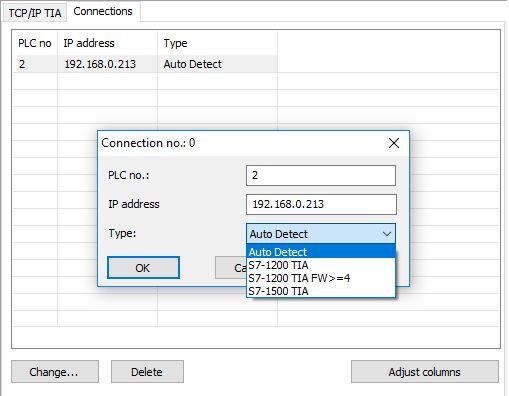
S7-TCP/IP TIA Connections panel
The Test tab
The Test tab allows the user to test a specific PLC connected to the selected Device.
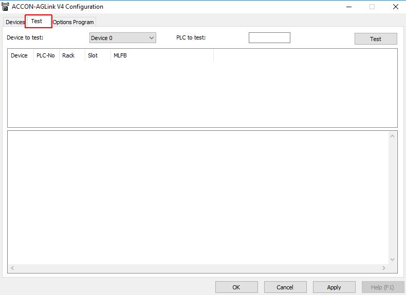
The Test tab
To test a PLC connection, the user must select the desired Device from the Device list, specify the PLC number of the PLC that needs testing and click the Test button.
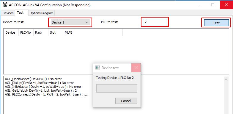
Testing PLC connection
If the test succeeds, no error will be displayed in the console and the connected PLC of the Device will be listed in the test grid.
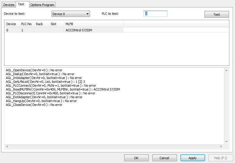
Successful PLC connection test
The Options Program
The Options Program dialog allows the user to organize following changes:
Language - allows the user to select the program language. Selection is done from the drop-down list, which contains by default the German and English languages.
Device count - allows the user to select the amount of devices displayed under the Devices tab. By default, the list is set to display 16 devices, but it can be changed to display 4, 8, 32, 64, 128 or 256 devices.
Ask to save the changed settings checkbox - if enabled, the i4scada Studio will ask the user to save the changed settings.
Settings directory - The settings done in the SIMATIC Connector's configuration tool will be saved in a predefined location, visible in the Options Program tab.
Program versions and Configuration - the information upon program versions and configuration is visible under the Options Program tab, allowing the user to copy the SIMATIC configuration from one Server to another.
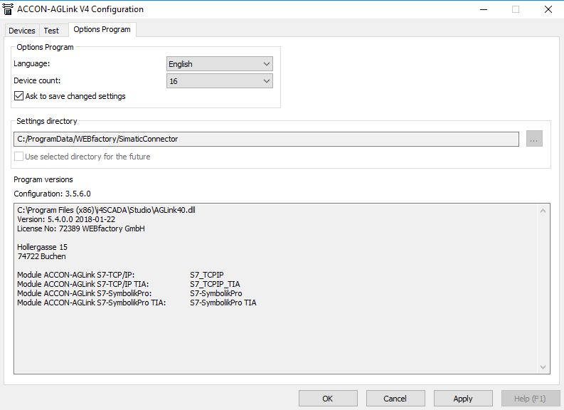
The Options Program tab
When processing changes at level of the Options Program, a dialog is displayed informing the user that changes will take effect next time the program is started.
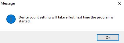
Message dialog
TIA Browse Settings
The TIA Browse Settings dialog lists all the TIA devices available in your current i4scada Studio project. Learn more about each setting in this view!
By clicking on the contextual menu option TIA Browse Settings a dialog is opened displaying the list of existing TIA devices.
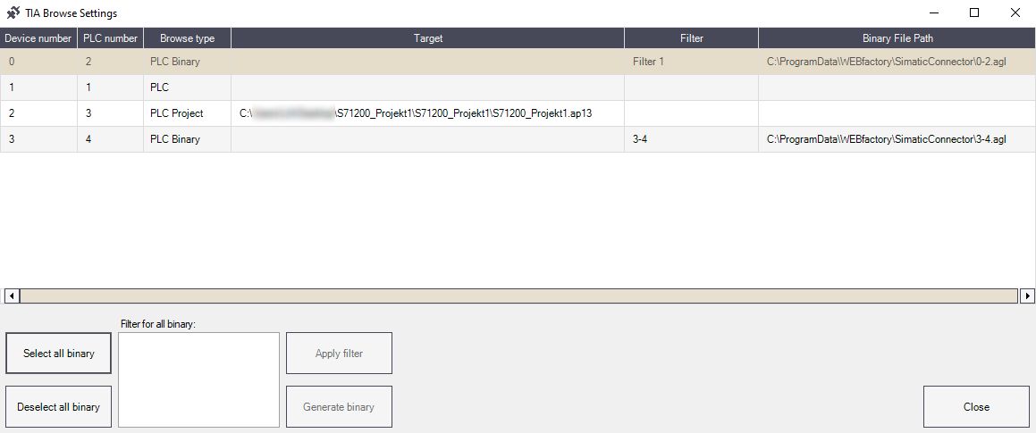
TIA Browse Settings dialog
The list is split up into the following columns:
Device number - the allocated device number.
PLC number - the allocated PLC number.
Browse type - the type of device browsing method:
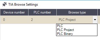
Browse types
PLC - the device connects to an actual PLC;
PLC Project - the device connects to a PLC Project, through an ap* file.
PLC Binary - the device connects to an actual PLC. Setting the Browse type to PLC Binary, allows the user to generate an *agl file.
Tip
When using the PLC Binary Browse type the user can manually define filters, with the scope to reduce the range of exposed PLC endpoints.
Tip
For faster and more reliable communication, the user is advised to use the PLC Binary Browse type, for TIA devices.
Target - allows the user to upload a target file, if the Browse type is set to PLC Project.
It is mandatory to add a target project, by clicking on the folder icon in the Target column.
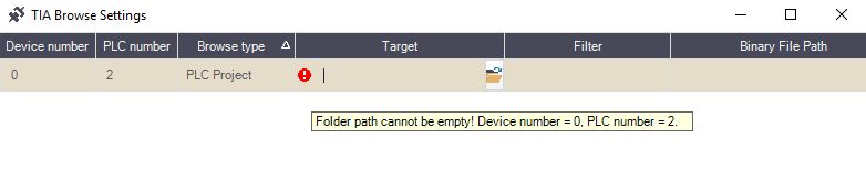
The folder path cannot be empty
By clicking the folder icon in the Target path column, the Select PLC project (ap*) file dialog is opened. To upload a project, the file must have the ap* format.
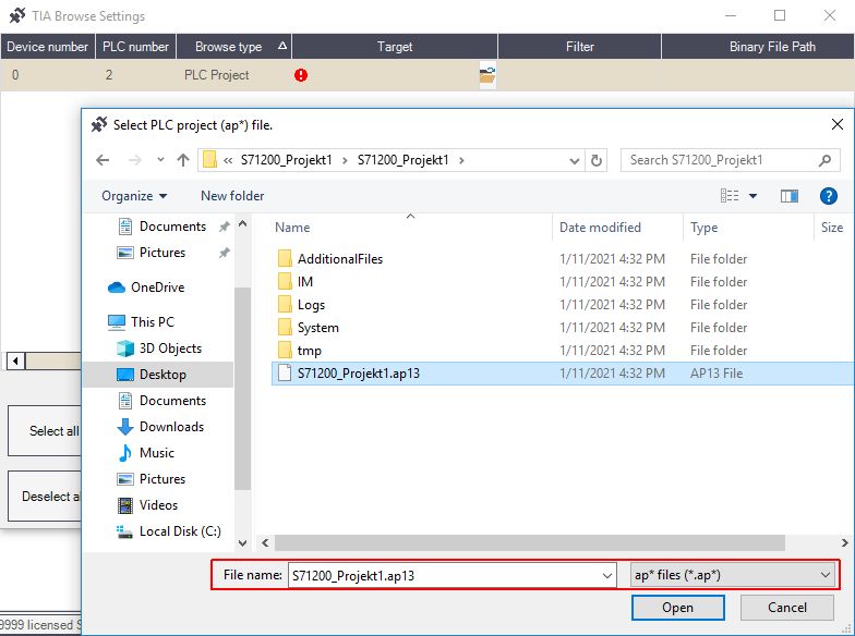
Upload the ap* file
Filter - allows the user to define filter(s) to lower the amount of exposed PLC endpoints, when the Browse type is set to PLC Binary.
Filters can be inserted by manually typing in the designated field the desired filter value.
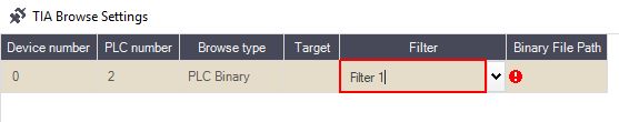
The Filter field
The user can also insert multiple filter lines, by expanding the filter field area.
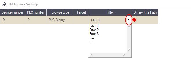
Multiple filters
Tip
Setting filter(s) prior to the generation of PLC binary files, reduces the amount of exposed PLC endpoints and consequently maximizes the general system performance.
Binary File Path - allows the user to upload a binary file, if the Browse type is set to PLC Binary.
It is mandatory to add a binary file, by clicking on the folder icon in the Binary File Path column.
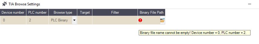
Binary File Path cannot be empty
By clicking the folder icon of the Binary File Path column, the Select binary file dialog is opened. To upload a project, the file must have the *.agl format.

The Select binary file dialog
The user can either keep the default file name, or change it, as desired. By default, the *.agl file name is self-generated on the basis of the following syntax: [Device number]-[PLC number].agl.
After setting up the binary file path, the user can proceed with generating the binary file, by clicking the Generate binary button.
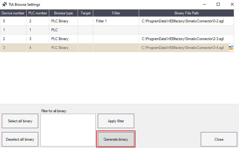
The Generate binary button
Since the generation of a *.agl file can be a long running operation, that runs in the foreground, the TIA Browse Settings dialog is equipped with a Cancel button, allowing the user to stop the operation.
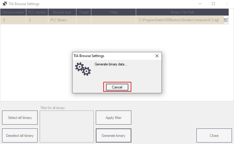
The Cancel button
Warning
Canceling the binary file generation may also be a long lasting operation.
The Binary generation operation is performed in a granular manner. Hence, if the file generation operation is canceled, the canceling will not take place immediately. The system will finish the file generation, for the running operation, keeping the TIA Browse Settings dialog, throughout the process, in a frozen state. Only the remaining operations will be canceled.
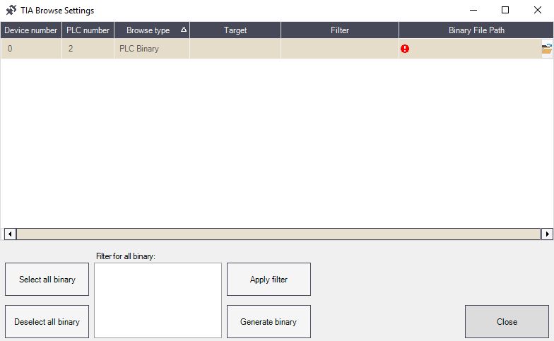
The bottom area of the TIA Browse settings dialog, features the following bulk management options, dedicated exclusively to the PLC Binary Browse type Devices:
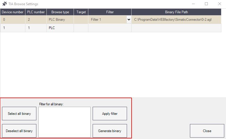
PLC Binary management options
Select all binary - applies the selection, to all the devices having the browse type set to PLC Binary.
Deselect all binary - removes the selection, of all the devices having the browse type set to PLC Binary.
Apply filter - applies the defined filter, to all the devices having the browse type set to PLC Binary.
Tip
The Apply filter option will ignore all other selected devices, that do not have the expected Browse type (PLC Binary).
Generate binary - starts the generation of the selected binary file(s). If multiple Devices are selected, the binary file generation will start for all of them.
Tip
The Generate binary option will ignore all other selected devices, that do not have the expected Browse type (PLC Binary).
Note
In case the binary file generation operation encounters errors, an Error window pops up, listing all the devices for which the generation was attempted.
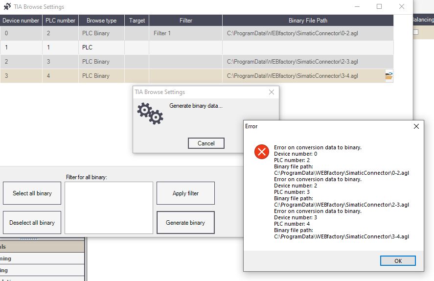
Example of error message, triggered for multiple devices
To learn more details about the reason for the operation failure, the Activity Analyzer tool should be used in parallel with Studio.
Filter for all binary -allows the user to manually define filters, that can be applied to multiple devices, having the browse type set to PLC Binary.
Tip
If no filter is specified in the dedicated area, all symbols are saved. However, as soon as a filter is specified, only symbols contained in it are saved. It is possible to filter PLCs, DBs, UDTs, tag tables as well as individual symbols. For example: "PLC_1".
"PLC_1.Blocks.DB_1" - all the symbols below this block will be displayed
"PLC_1.UDTs"
"PLC_1.Tags"
It is also possible to use wildcard filtering. The "*" character can be used to indicate that any text can be placed at this position, in this path section. For example: e.g.: "PLC_1.Blocks.DB_*" All data blocks of PLC_1 are used which begin with "DB_". To save all the tag tables, the user can use the "*.Tags" filter.
To escape characters, the double quotation marks ("") can be used, as in this example: "PLC_123" "PLC*_123". To apply multiple filters, the newline ("\n") character can be used, as follows: "PLC:1.Blocks.DB_1\nPLC_2.Tags.Table_1.bool.variable". However, by hitting the enter keyboard button, a new line is automatically generated as in the below example:
filtercontion.one*
filtercontion.two
After setting up the browse type for all the TIA devices, the TIA Browse Settings dialog can be closed, by clicking the Close button.
Close TIA Browse Settings dialog
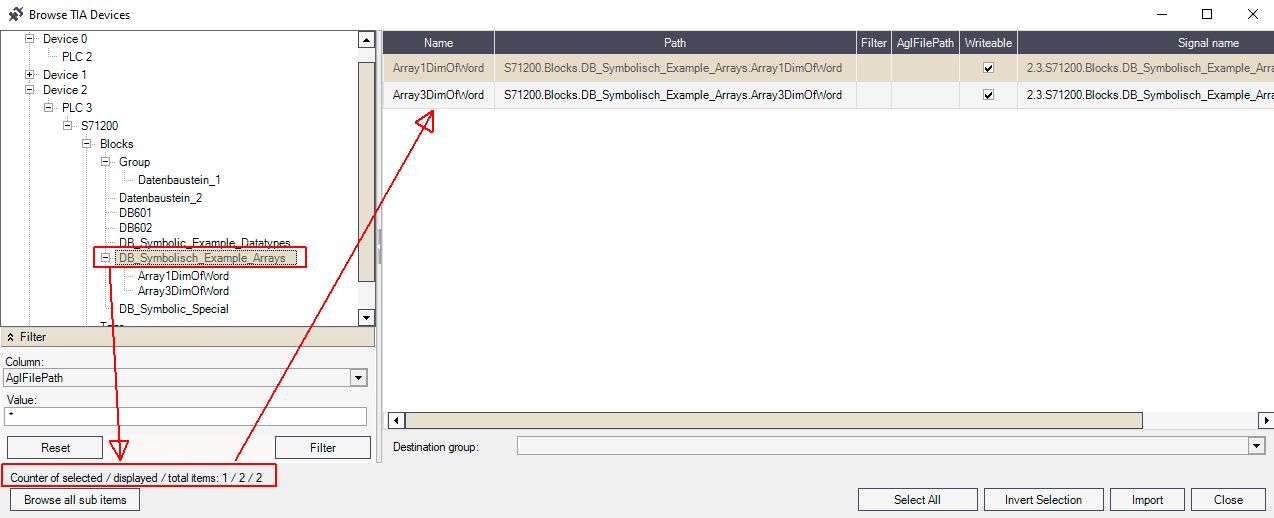
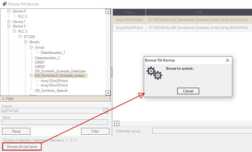
Browse TIA devices
The Browse TIA devices dialog allows you to check your devices in a hierarchical view, where multiple management actions are available.
The Browse TIA devices option in the SIMATIC Connector contextual menu opens the dialog where the user can browse for TIA devices.
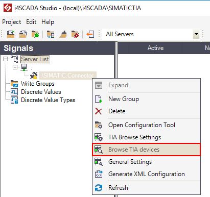
Browse TIA devices contextual menu
The Browse TIA Devices dialog is split up in four main panels:
The devices hierarchical view panel
The grid view panel
The filter panel
The actions panel
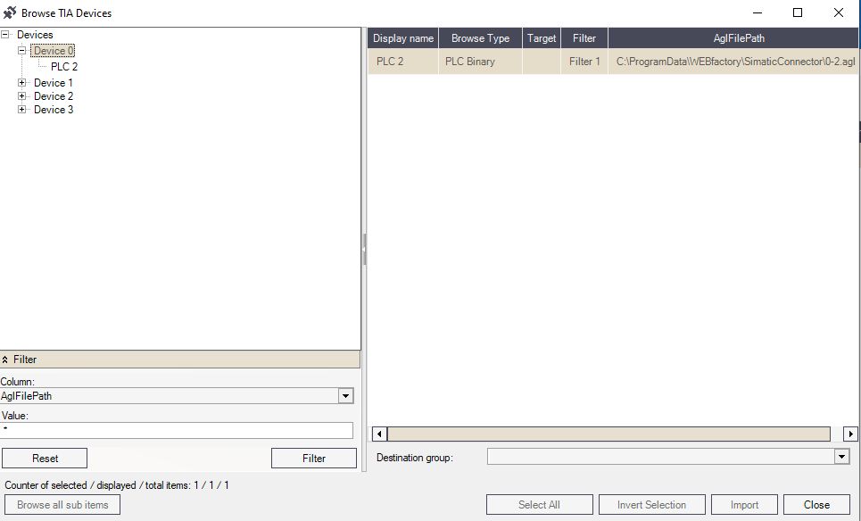
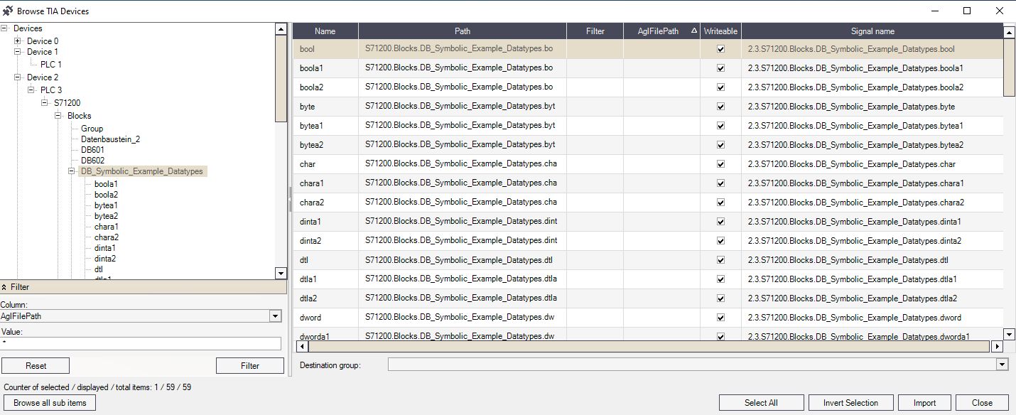
The Browse TIA Devices dialog
In this view, the user can browse for TIA specific symbols to use them as Ewon by HMS Networksi4scada signals.
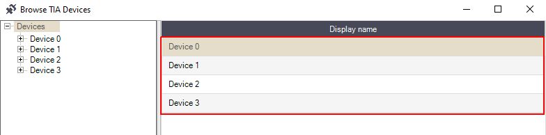
The hierarchical list of devices
At the top left side of the Browse TIA Devices dialog, the hierarchy of all available TIA devices is displayed.
The user has the possibility to expand the hierarchy, by clicking on the tree nodes, until reaching the TIA Symbols.
Tip
Some of the hierarchical nodes are not subscriptable, but their children can be.
The hierarchy nodes can also be vertically collapsed and expanded by means of the plus and minus signs.
The devices hierarchy
The grid view
The second panel in the Browse TIA Devices dialog is given by the Grid view. Here, the user can view the following information:
The Grid view of the Devices (when the user is positioned on the hierarchy root node "Devices").
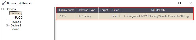
The Grid view of the PLCs of a Device (when the user is positioned on the Device# node).
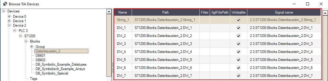
The Grid view of the TIA Symbols (when the user is positioned on a node containing Items).
The Grid view does not provide the user with the possibility to perform further actions, as its scope is purely informative.
The filter panel
The filter panel allows the user to filter the items displayed in the hierarchical view.
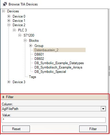
The Filter panel
The filter criteria is based on the Columns and the Values of the Grid view, as follows:
Filter Devices
Column - Display name.
Value - the name of the Device.
Filter PLCs
Column - AglFilePath, Browse Type, Display name, Filter and Target.
Value - the browse type, the name of the device, and the target path.
Filter TIA Symbols
Column - AglFilePath, Browse Type, Display name, Filter and Target.
Value - The name of the Symbol, the target path, the inherited signal name, and the writable attribute.
Once the desired criteria is set, the user can click the Filter button to apply the filter to the Grid view. A funnel symbol will be displayed in the Filter panel header, as long as a filter is active.
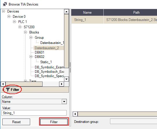
Filter applied
To remove the filter, the user can click on the Reset button. Automatically the filter is removed and list of results in grid view is updated.
The actions panel
The actions panel of the Browse TIA Devices dialog is located at the bottom of the pop-up window.
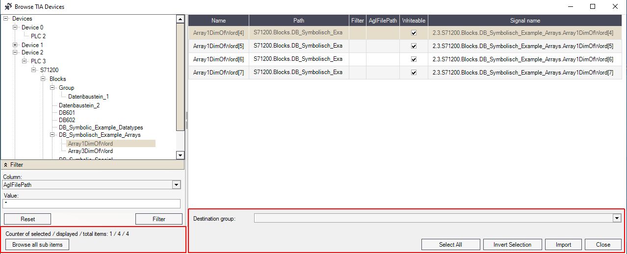
The Actions panel
Here, the user has following actions available:
Info message referring to the total number of items. The system will display the total amount of items subordinated to the currently selected node.
Browse all sub items button - this option allows the user to load the grid view with all the items and sub items of the currently selected node.
Note
When pressing the Browse all sub items button, a console will pop up. Given the fact that some nodes may have multiple children and grandchildren inheriting items, the browse action may be time consuming.
The user may decide to press the Cancel button to abort the browse action. In this case, the grid view will display only the items that were loaded until the cancel occurred.
Further on, the browser cache will temporarily store the loaded Items, so, on a new browse action the loading time will be reduced.
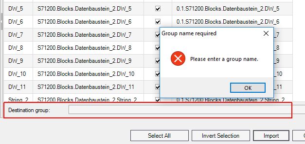
Destination group - In order to be able to import Symbols and use them as Ewon by HMS Networksi4scada Signals, at least one Group should be available. The Destination group field will act in this case either as a group selector (drop-down list) or as a free text field, where the user can type the name of the new signal group.
Select all button - the Select all button becomes active as soon as at least one TIA Symbol is selected in the grid view. By clicking this button, all the listed Items will be selected.
Invert Selection button - the Invert Selection button becomes active as soon as at least one TIA Symbol is selected in the grid view. By clicking this button, the current selection is inverted and all deselected Items will be marked and vice-versa.
Import button - the Import button becomes active as soon as at least one TIA Symbol is selected in the grid view. By clicking this button, the system will import the selected Symbol(s) and use them as Ewon by HMS Networksi4scada Signals. In order for the Import to be processed, it is mandatory that a destination group is defined. Otherwise, an error console will pop-up.
Close button - closes the Browse TIA devices dialog without processing any changes.
General Settings
The General Settings dialog allows you to check all the SIMATIC Devices, regardless of their type. Check out what additional settings you can organize in this view.
In the General Settings contextual menu of the SIMATIC Connector, the user can see the list of all SIMATIC Devices, regardless of their type.
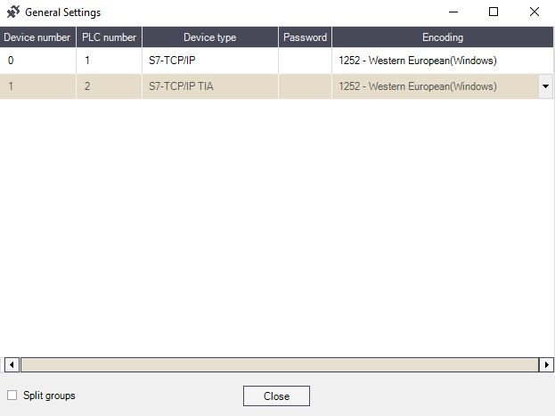
General Settings dialog
In this list, the user can change the Device Encoding type. By default, the Western European (Windows) encoding is set, but many others can be selected from the drop-down list.
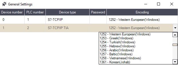
Encoding selector
Note
The changes at the level of the Encoding type will be preserved ONLY if the selected Device has a Signal Group defined.
The Split Groups check-box is by default disabled. By enabling this check-box, the system will generate the Signal polling for each existing Group, independently from each other.
By clicking the Close button the General Settings dialog is closed and any changes organized here, will be preserved.
Generate XML Configuration
Save your progress by means of the Generate XML Configuration option, available exclusively for the i4scada SIMATIC Connector.
The Generate XML Configuration contextual menu of the SIMATIC Connector, acts as a save operation.
Generate XML Configuration
Whenever the SIMATIC Configuration is changed, a warning icon will be applied to the Connector node, hence, notifying the user that the XML configuration requires a new generation.
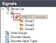
SIMATIC Connector warning icon
As soon as selecting the Generate XML Configuration the SIMATIC Connector warning icon is removed. Consequently, an XML configuration is generated, based on the settings applied to the SIMATIC connector in i4scadaStudio.
Important
The user must Generate XML Configuration whenever the SIMATIC connector configuration has been changed!
i4scada SNMP Connector
Learn more about the SNMP Connector and the settings required to configure it on your i4scada machine, by reading this article.
The SNMP connector is a WEBfactory i4scada connector that uses the Simple Network Management Protocol (SNMP) to connect to various devices located on a Windows machine or remotely to non-Windows devices (routers, switches, hubs, etc.).
In order to use the SNMP Connector the following changes need to be organised:
Tip
For a set of step-based tutorials, please also visit the articles under the i4scada SNMP Connector Tutorials.
Enable SNMP for Windows
Check out this article in order to learn how to enable the Simple Network Management Protocol (SNMP) in Windows.
To enable the Simple Network Management Protocol (SNMP) on a Windows machine, please follow the next steps:
Using the Start menu search box, type "Turn Windows features on or off" and open the Windows Features dialog.
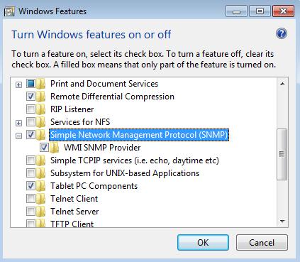
Turn Windows features on or off
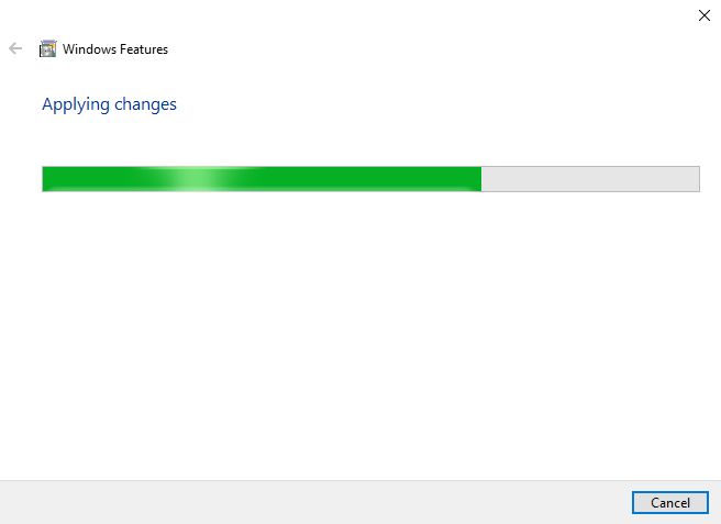
Go to Simple Network Management Protocol (SNMP) and mark both Simple Network Management Protocol (SNMP) and WMI SNMP Provider for installation. Select OK to confirm. The system will start applying the changes.
Now that the SNMP feature is on, we need to configure the SNMP service to work with the SNMP Connector. In the Start menu search box, type "Component Services" and open the Services window.

Services window
Find the SNMP Service and double click it to edit its properties. In the new SNMP Service Properties window, go to the Security tab.
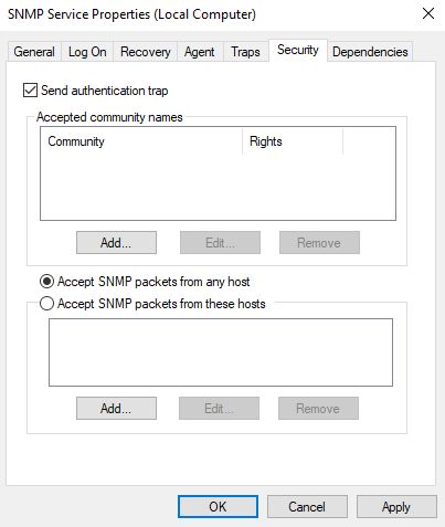
SNMP Service Properties window
Note
The SNMP packets can be accepted from any host or from hosts defined by IP/IPX addresses
The security features of the SNMP Service must be set up in order to give access to the SNMP Control of i4scada Studio to the data passed by this service. To do so, we need to create a Community that has privileges to Read and/or Write the data received from the desired component via the SNMP Service. In the Accepted community names section, click on the Add button.
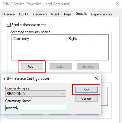
SNMP Service Configuration
Select a Community right from the drop-down combo box and give a name to the new community (for tutorial purposes, the name will be read only).
Click on Add to add the new community and confirm by pressing OK in the SNMP Service Properties window.
Tip
Later on, in i4scada Studio we will use this community name in the SNMP Connector to have access to read the components data via this protocol.
Tip
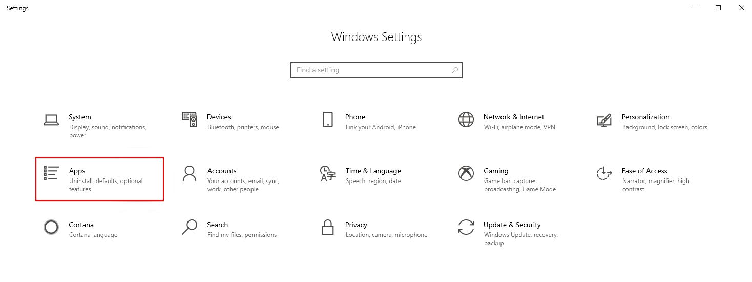
If you have Windows 10 1809 OS build 17763.xxx, the SNMP Settings can be enabled, as follows:
Using the Start menu search box, type "Settings" and open the Windows Settings panel. Click on the Apps option.
In the Apps & features window click on Optional features.
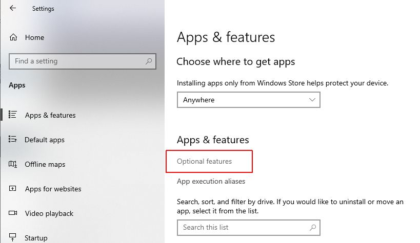
In the Optional features window click on the Add feature button.
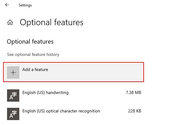
Scroll to the listed features and identify the following features:
Simple Network Management Protocol (SNMP)
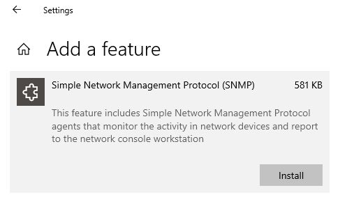
WMI SNMP Provider
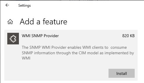
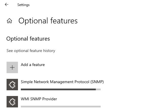
Install both of these features.
i4SCADA Studio settings
Check out this article and learn how to configure the i4SCADA Studio settings in order to use the SNMP Connector properly.
An empty SNMP Connector will look like this:
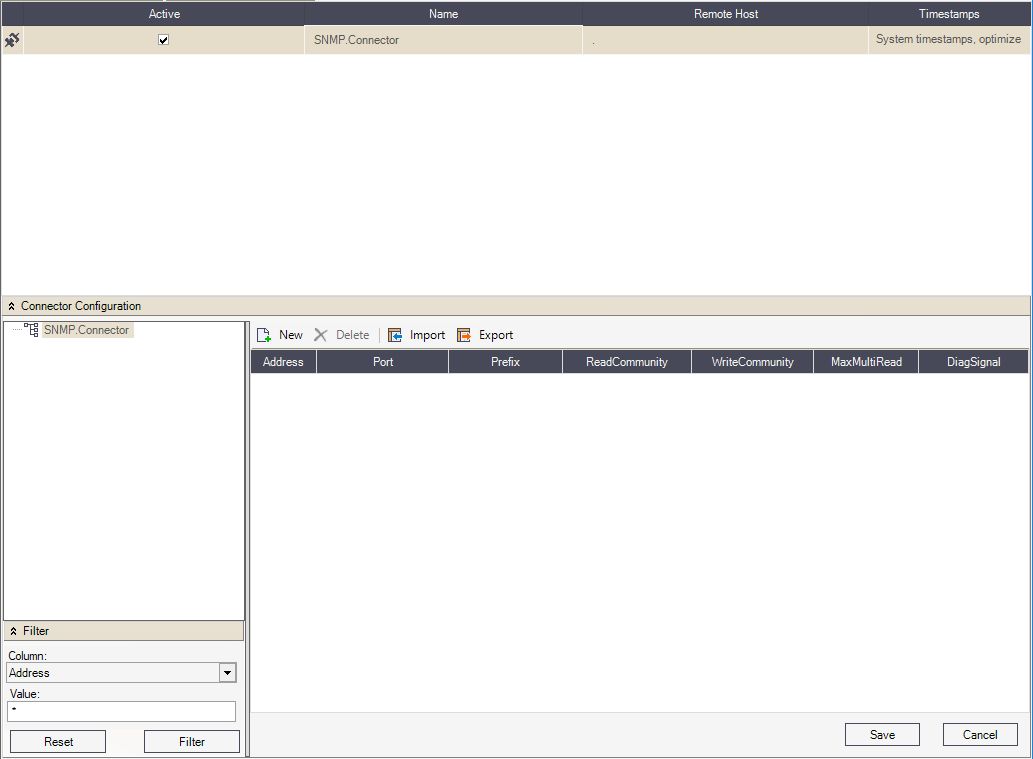
Empty SNMP Connector configuration
The SNMP Connector Configuration panel menu allows the user to add a new object, delete the selected object, and import/export configurations.
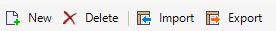
New - Adds a new SNMP device or signal.
Delete - Deletes the selected object.
Import - Imports a configuration from an SNMP configuration file.
Export - Exports the configuration to an SNMP configuration file.
Tip
The SNMP Connector configuration is based on a connection machine and its Signals (Data Outputs). Please also check our step-based tutorials, here.
In order to create a machine connection in the SNMP Connector, the user can click on the New toolbar button, from the Connector Configuration panel.
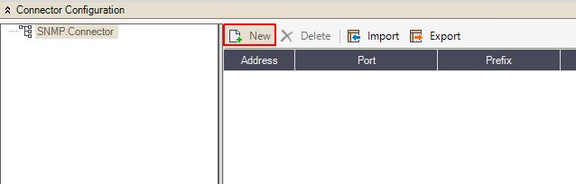
Create a new machine connection
A new machine connection will be added to the SNMP Connector allowing the user to configure its properties.

The new SNMP machine connection
The properties of the machine connection allow the user the define the following settings:
Address - The network address (IP) of the machine that holds the device.
Port - The network port to use. The default value is 161.
Prefix - The prefix of the machine connection.
ReadCommunity - The community name authorized to read the data from the device. This was set up before, in the SNMP Service.
WriteCommunity - The community name authorized to write the data from the device. This was set up before, in the SNMP Service.
MaxMultiRead - The maximum number of read commands in one packet.
DiagSignal - The diagnose signal.
By clicking on the SNMP machine connection, all the available Signals, also known as Data Outputs, will be listed. New Data Outputs can be created by using the toolbar button New. The SNMP Signals feature the following properties:

The SNMP Data Outputs
Name - The name of the signal (data output).
Oid - Object Identifiers uniquely identifying managed objects in an MIB (Management Information Base: a collection of information organized hierarchically) hierarchy.
Syntax - The method of interpreting the data. Can be:
SNMP_BITS
SNMP_CNTR32
SNMP_CNTR64
SNMP_GAUGE32
SNMP_INT32
SNMP_IPADDR
SNMP_OCTETS
SNMP_OID
SNMP_OPAQUE
SNMP_TIMETICKS
SNMP_UINT32
Coding - The Signal encoding. Can be
None
Hexstring
Writeable - If checked, the data can be writable.
Period (milliseconds) - The read periodicity of the data, expressed in millisecond