i4scada SIMATIC Connector Tutorials
To help you configure your i4scada SIMATIC Connector check out these tutorials where the settings for both S7-TCP/IP and S7-TCP/IP TIA devices are available.
Configuring an S7-TCP/IP device
You are just a few steps away from using the i4scada Simatic Connector with an S7-TCP/IP device. Check out this article!
Tip
For more details regarding the SIMATIC Connector, please visit the dedicated article, here.
To configure an S7-TCP/IP device, the user can organize the following steps:
Open the i4scada Studio.
Create a new database "SIMATIC".
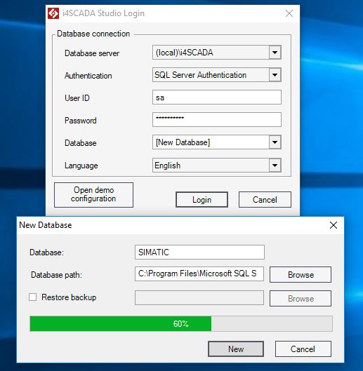
Log into the i4scada Studio.
Under the Signals area, click right on the Server List node and select the New Server contextual menu option.
New Server is added.
Note
If the Server runs on the same machine as the Studio, the Server name must be "." (the period character).
Click right on the Server node and select the New Connector contextual menu option.
Select from the list of connectors the SIMATIC Connector.
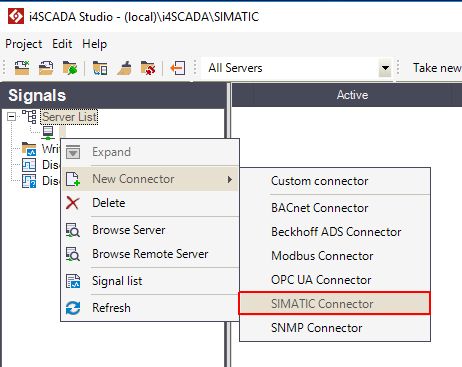
The SIMATIC Connector is added to the Server.

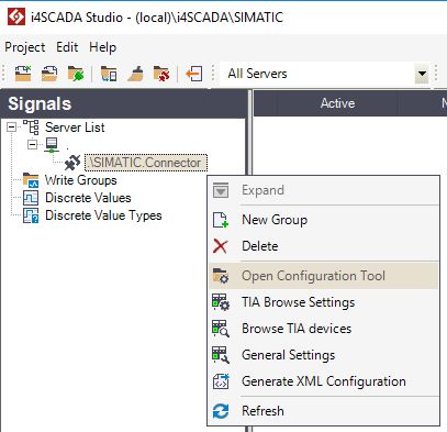
Click right on the SIMATIC Connector node and select the Open Configuration Tool option.
The ACCON-AGLink V4 Configuration window is opened. Under Devices tab, select Device 0 the S7-TCP/IP option.
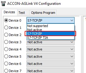
Configure the S7-TCP/IP Device, by filling in the desired settings under TC/IP and Connection tabs.
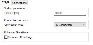

Save the changes made by clicking the buttons Apply and OK.
Click right on the SIMATIC Connector node and select Generate XML Configuration option, to preserve the Device changes, at the level of the Connector.
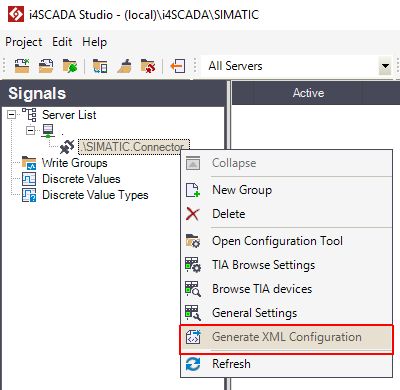
Next, right click on the SIMATIC Connector and select the New Group option.
New Group is added to the Server List hierarchy.
Right click on the Group1 node and select the New Signal option.
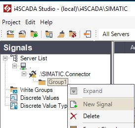
The new signal is added to the list. Proceed by configuring the S7-TCP/IP Signal.
Note
To set up signals inside i4scada Studio for the SIMATIC Connector, a special format must be used in the signal's Connector address. The signal's connector address is composed of three important data:
the Device number - the Device number from the SIMATIC Connector's configuration tool
the PLC number - the PLC number from the SIMATIC Connector's configuration tool
the data type - see list below
The signal's connector address will look like this:
"Device_number"."PLC_number"/"data_type"
"Device_number"."PLC_number"\"data_type"
The separator used between the Device_number and the PLC_number will always be "." (dot), while the separator used between the PLC_number and the data_type can be either "\" (back-slash) or "/" (forward-slash).
For more details regarding S7-TCP/IP Signals supported data types, please refer to The Data types table.
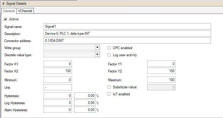
Save the Signals Group, by clicking the Save button.
To preserve the changes at the level of the connector, right click on the SIMATIC Connector node and select the Generate XML Configuration option.
Configuring an S7-TCP/IP TIA device
You are just a few steps away from using the i4scada Simatic Connector with an S7-TCP/IP TIA device. Check out this article!
Warning
If using the TIA Portal V17, please note that Secure PG/PC and HMI communication is not supported.
The check mark must not be set, otherwise, the communication will not work.
To configure an S7-TCP/IP TIA device, the user can organize the following steps:
Open the i4scada Studio.
Create a new database "SIMATIC".

Log into the i4scada Studio.
Under the Signals area, click right on the Server List node and select the New Server contextual menu option.
New Server is added.
Note
If the Server runs on the same machine as the Studio, the Server name must be "." (the period character).
Click right on the Server node and select the New Connector contextual menu option.
Select from the list of connectors the SIMATIC Connector.

The SIMATIC Connector is added to the Server.

Click right on the SIMATIC Connector node and select the Open Configuration Tool option.

The ACCON-AGLink V4 Configuration window is opened. Under Devices tab, select Device 1 the S7-TCP/IP TIA option.
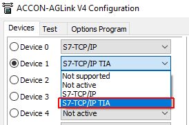
Configure the S7-TCP/IP TIA Device, by filling in the desired settings under TC/IP TIA and Connection tabs.
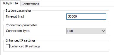

Save the changes made by clicking the buttons Apply and OK.
Right click on the SIMATIC Connector node and select the TIA Browse Settings option.
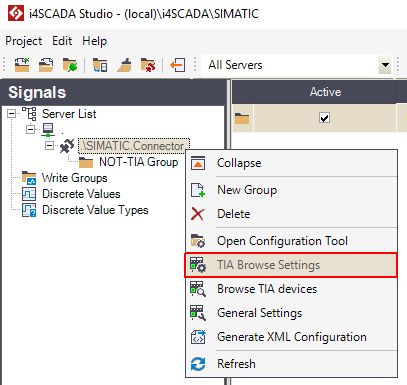
The TIA Browse Settings window is opened. Select the PLC Project option, under the column Browse type.
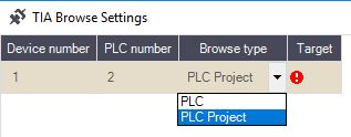
In the Target column, set up the PLC Project for your TIA device.

Close the TIA Browse Settings window.
Next, right click on the SIMATIC Connector node and select the Browse TIA Devices option.
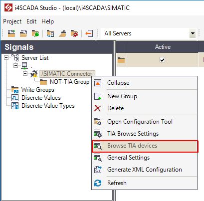
The Browse TIA Devices window is opened. Expand the hierarchy until reaching the desired TIA Symbols.
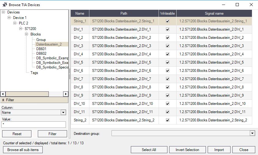
Fill in a new Group in the Destination group field.
Select the desired TIA Symbols and press the Import button.
Close the Browse TIA Devices window when all the desired TIA Symbols have been imported to your destination group.
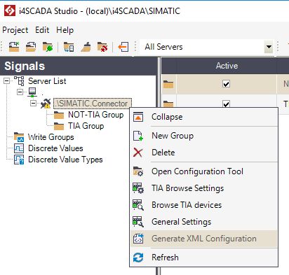
To preserve the changes at the level of the connector, right click on the SIMATIC Connector node and select the Generate XML Configuration option.
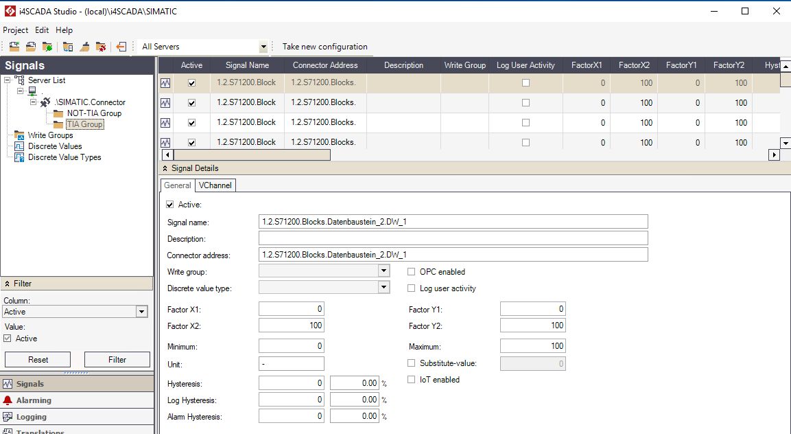
Select the TIA Symbols group. All the imported TIA Symbols have been added to the list, converted into TIA Signals.
Importing signals for the SIMATIC Connector
Check out this article and learn more details about the Import signals functionality and how it behaves for both TIA and non-TIA devices.
The Import signals functionality can be used to import signals for both TIA and non-TIA devices, as described in the two sections below.
Tip
Since i4scada 3.8.12 version, this import only validates the following facts:
what type of device does the import introduce (TIA or non-TIA);
if the PLC number exists, in the SIMATIC Connector's configuration tool;
if the Device number exists, in the SIMATIC Connector's configuration too.
Import signals to a non-TIA Device
As already indicated, the signal's connector address is composed of three important data:
the Device number - the Device number from the SIMATIC Connector's configuration tool
the PLC number - the PLC number from the SIMATIC Connector's configuration tool
the data type - see the complete list here.
The signal's connector address will look like this:
"Device_number"."PLC_number"/"data_type" or "Device_number"."PLC_number"\"data_type"
When a high amount of signals needs to be added to i4scadaStudio, but manual work is not desired, the user can proceed as follows:
Open Studio and expand the server, until reaching your group of signals, available on the SIMATIC connector.
Select the desired Signal(s) and click the right mouse button.
Tip
At this step, we are selecting one or multiple signals that already have the connector address(es) that we need to use.
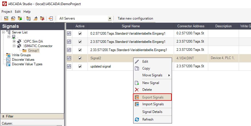
Select the Export Signals option, from the opened contextual menu.
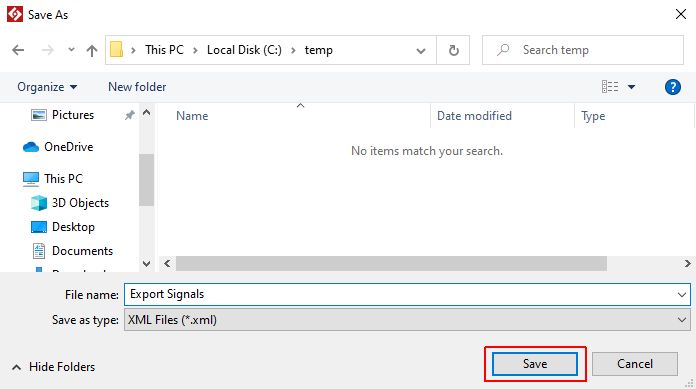
The Save As dialog is opened, allowing you to choose the location where the export file is to be saved.
After choosing a known and accessible location, click the Save button.
Tip
The files will be saved in XML format.
Visit the selected location and open the Signals XML file, using a spreadsheet application (like Microsoft Excel). Start adding the needed signals and make sure to save the file, after finishing your work.

Tip
Spreadsheet applications provide a better overview of the exported data and allow the user to easily rework the data that will be re-imported, into Studio.
Return to the Studio application and click the right mouse button, of your SIMATIC Connector's Signals grid view area.
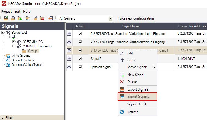
Select the Import Signals option.
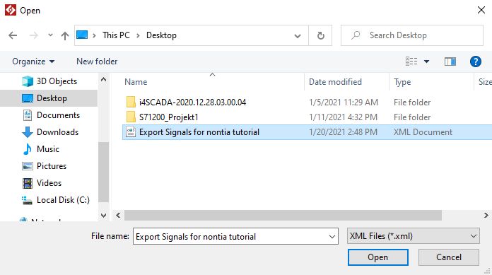
The Open dialog is opened, allowing you to select and apply the previously updated signals file.
Click the Open button to start the signals import.
The Import Signals panel is opened, listing all the Signals contained by the imported file.
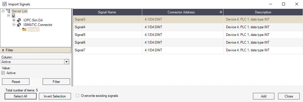
Select all the Signals that need to be uploaded to Studio and click the Add button.
A pop-up confirmation dialog is displayed, providing more information about the import results.
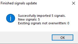
Warning
The Studio application does not validate the imported signals. This responsibility falls back to the SIMATIC Connector, which reacts after the user generates the XML configuration. If the import is rejected, a warning message will be displayed, at this step.
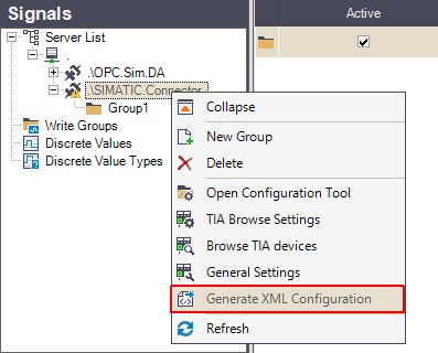
The list of Signals is updated, displaying the imported Signals, as well.
Import signals to a TIA Device
Adding Signals to a TIA Device can be a long lasting operation, as it relies on the Browse TIA Device function. Hence, the user can decide to update a TIA Device's Signals list, by means of import, as follows:
Open Studio and expand the server, until reaching your group of signals, available on the SIMATIC connector.
Select the desired Signal(s) and click the right mouse button.
Tip
At this step, we are selecting one or multiple signals that already have the connector address(es) that we need to use.
Select the Export Signals option, from the opened contextual menu.

The Save As dialog is opened, allowing you to choose the location where the export file is to be saved.
After choosing a known and accessible location, click the Save button.
Tip
The files will be saved in XML format.

Visit the selected location and open the Signals XML file, using a spreadsheet application (like Microsoft Excel). Start adding the needed signals and make sure to save the file, after finishing your work.

Tip
Spreadsheet applications provide a better overview upon the exported data and allow the user to easily rework the data that will be re-imported, into Studio.
Return to the Studio application and click the right mouse button, of your SIMATIC Connector's Signals grid view area.
Select the Import Signals option.

The Open dialog is opened, allowing you to select and apply the previously updated signals file.
Click the Open button to start the signals import.
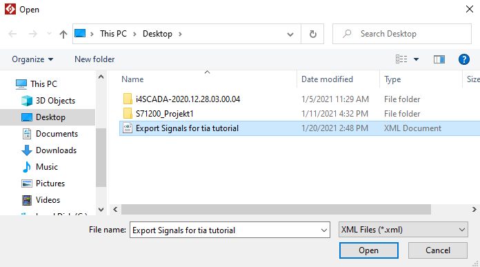
The Import Signals panel is opened, listing all the Signals contained by the imported file.

Select all the Signals that need to be uploaded to Studio and click the Add button.
A pop-up confirmation dialog is displayed, providing more information about the import results.

Warning
The Studio application does not validate the imported signals. This responsibility falls back to the SIMATIC Connector, which reacts after the user generates the XML configuration. If the import is rejected, a warning message will be displayed, at this step.

The list of Signals is updated, displaying the imported Signals, as well.