Adding Devices
Check out this article and learn how to add new devices and everything that you need to know about the device type-dependent settings.
In order to be allowed to create new devices, the user must have the Manage devices permission enabled.
The Add button from the top menu of the Device List panel allows the user to add new devices to the Device List. Clicking the Add button opens the Select Device Type panel, allowing the user to choose which device type to create.
Tip
The Add new Device button will only be displayed in the Device List when the user is in the context of a hierarchical entity (Areas, Organizational Units, Sites).

The Select Device Type panel
Selecting a device type opens the Add Device panel, where the user can input the device settings.
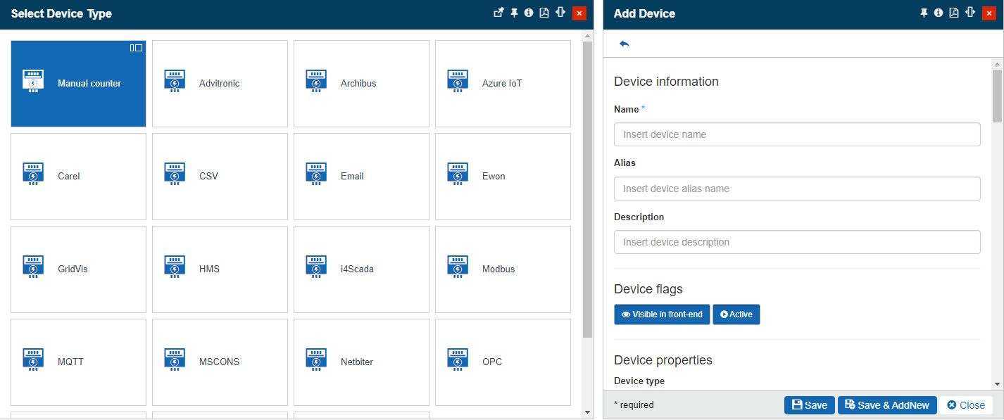
The Add Device panel
The device settings are split up into two categories:
Default device settings (available for any device type)
Category | Property | Description |
|---|---|---|
Device information | Name | The unique technical name of the device. This field will be mandatory regardless of the selected Device type. |
Alias | The friendly name of the device. The Device Alias will be displayed on the device card when listed. | |
Description | The description of the device. | |
Device flags | Visible in front-end | If enabled, the device will be listed in the i4connected portal. |
Active | If enabled, the device will be active. | |
Device properties | Device type | The device sub-type can be defined by the user. The user can select the desired Device type from the Device types panel. In this view, all the available device types are listed. 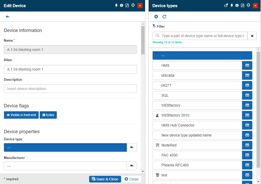 Further on, the users can edit the listed device types or add new ones. When adding a new Device type, the user is required to define a name and select an icon. The icon is selected from the Select icon panel where multiple predefined icons are available. 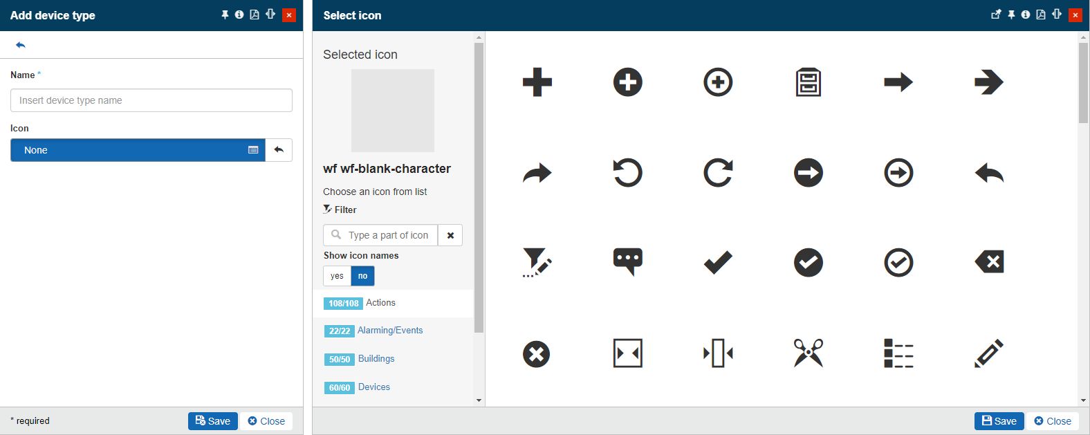 ImportantThe Device type icon will be displayed for the Device to which the Device type is used, in multiple contexts, such as: |
Manufacturer | The manufacturer of the device. The user can select the desired Manufacturer from the Device manufacturers panel. In this view, all the available manufactures are listed. 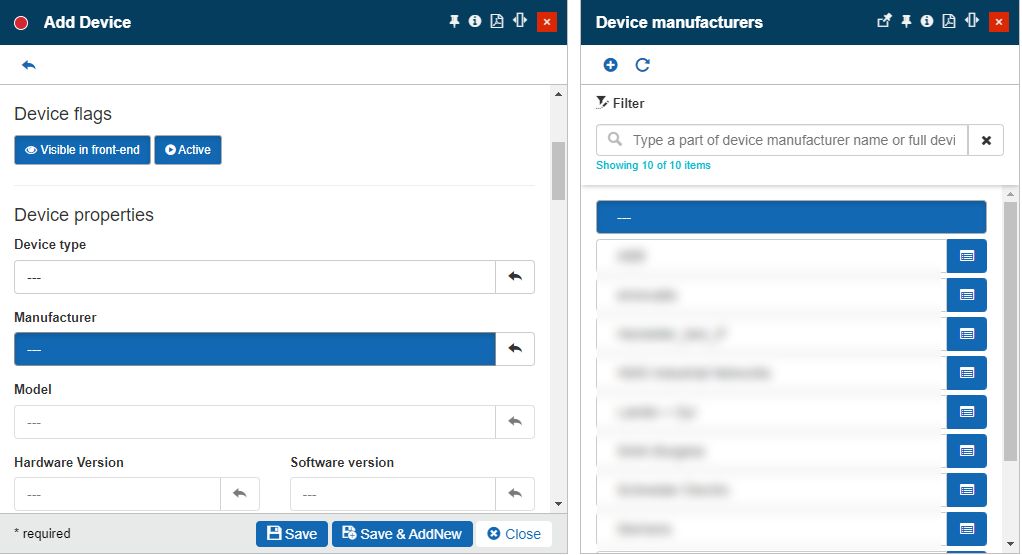 Further on, the users can edit the listed manufacturers or add new ones. When adding a new Manufacturer, the user is only required to define a name. 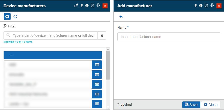 | |
Model | The model of the device. The user can select the desired Device Model from the Device Models panel. In this view, all the available manufacturers are listed. 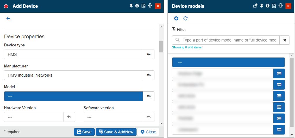 WarningThe Model selector becomes active only after adding a Device type and a Device Manufacturer. Further on, the users can edit the listed models or add new ones. When adding a new model, the user is only required to define a name. 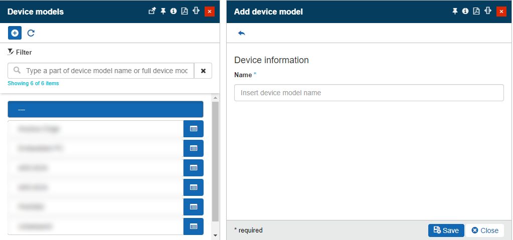 | |
Hardware version | The hardware version of the device. The user can select the desired Device Hardware Version from the Device hardware version panel. In this view, all the available hardware versions are listed. 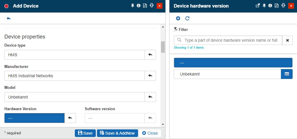 WarningThe Hardware version selector becomes active only after adding a Device model. Further on, the users can edit the listed hardware versions or add new ones. When adding a new hardware version, the user is only required to define a name. 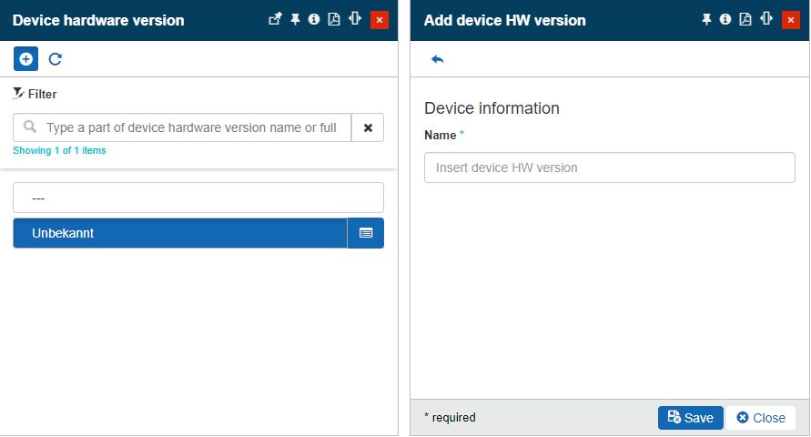 | |
Software version | The software version of the device. The user can select the desired Device Software version from the Device software version panel. In this view, all the available hardware versions are listed. 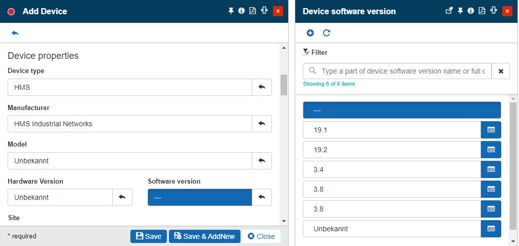 WarningThe Software version selector becomes active only after adding a Device model and a Hardware version. Further on, the users can edit the listed software versions or add new ones. When adding a new software version, the user is only required to define a name. 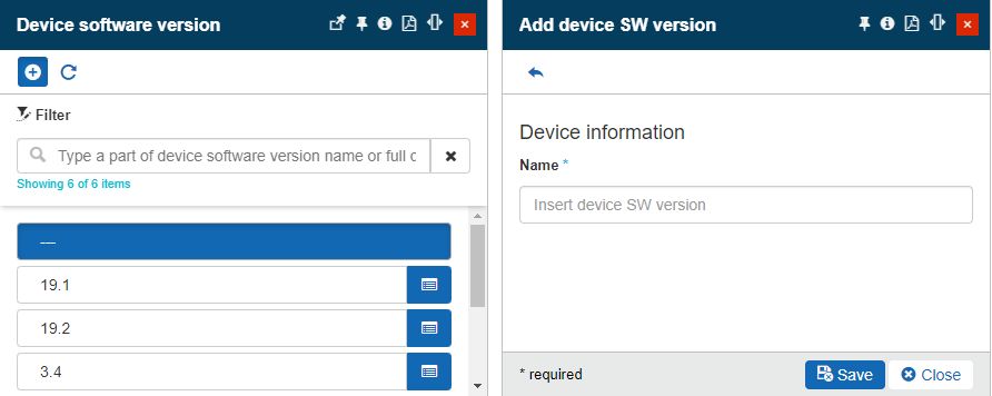 | |
Site | The Site where the device is installed. The Site can be selected from the Object filters panel, which is automatic.  NoteIf the Add device panel was accessed in the context of a Site, that Site will be by default set in this field. | |
Area | The Area where the device is installed.  NoteIf the Add device panel was accessed in the context of an Area, that Area will be by default set in this field, along with its parent Site. | |
Organizational Unit | The Organizational Unit to which the device belongs.  NoteIf the Add device panel was accessed in the context of an Organizational Unit, that Organizational Unit will be by default set in this field. | |
Overwrite event priority | Allows users with the possibility to select a priority that will be, by default, applied to all events triggered in the context of the current Device. 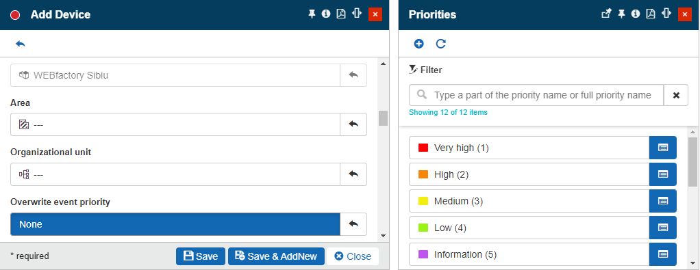 The selected priority will overwrite the original priority of the event. If the event has no priority defined, the overwritten event priority will be applied. TipThe priority selected at the level of a Device, under "Overwrite event priority", can only be surpassed when manually triggering an event, in the context of that Device. The Publish Manual Event panel allows the user to either trigger the event using an explicit priority, or leave the "Use the system default" option. For more details about the management of manual events, please refer to the dedicated article, here. Further on, you can also check out this tutorial, describing the overwrite event priority feature. | |
Alarm suppression | Suppression Mode Manual | Allows users the possibility to suppress alarms for a Device, by enabling the Manual mode.  When alarm suppression is Enabled for a device, all event occurrences that would have been triggered by the device will be completely ignored by the system. They will not be shown in the online alarms panel and they will not be saved in the historical alarms list. In Manual mode, as long as the toggle button is in the "Enabled" position, alarms for the device will be suppressed. TipFor more details, please also read the dedicated tutorial, here. |
Suppression Mode Scheduled | Allows users the possibility to suppress alarms for a Device, for a certain time interval, by enabling the Scheduled mode. 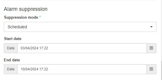 When alarm suppression is turned on for a device, all event occurrences that would have been triggered by the device will be completely ignored by the system, during the scheduled time interval. They will not be shown in the online alarms panel and they will not be saved in the historical alarms list. In Scheduled mode, alarms for the device will be suppressed during the selected start and end dates. After the end date, the alarms flow will be resumed. TipFor more details, please also read the dedicated tutorial, here. | |
Photo | The photo of the device itself.  | |
Installation photo | The overview photo of the device installation location.  | |
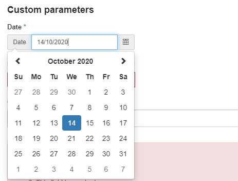
Custom parameters | If no Custom field definitions were specified for Devices, the Custom parameters area will be hidden from the Add / Edit device panel. As soon as at least one Custom field definition is available, the Custom parameters area allows the user to fill in the Device's metadata, as described below. For more details on the Custom field definitions validation rules, please also visit the dedicated article here. The following list depicts the possible Custom field definitions:
| |
Type dependent settings
The following device types require additional settings besides the standard ones listed above. These additional settings are usually focused under the Adapter category.
Note
For more details regarding each Adapter type and their specific settings, please also visit the Adapters configuration article.
Section | Property | Description |
|---|---|---|
IoT Hub settings | IoT Hub name | The name of the i4connected IoT Hub. It is mandatory to provide data for this field. |
Filter | The filters which parse the data received from the IoT Hub | |
Device Id | The identification number of the device. | |
Direct method of device | Method Name | The name of the method which should be called. |
Method Payload | The JSON payload method. | |
Method response Timeout in Seconds | The timeout, expressed in seconds, for waiting for a response from the method (min: 0 / max: 300, default: 120) | |
Method Connection Timeout in Seconds | The timeout, expressed in seconds, for waiting for the IoT device connection (min: 0, default: 0, cannot be more than the Method Response Timeout in Seconds. |
Section | Property | Description |
|---|---|---|
CSV settings | CSV source | The name of the CSV server providing the data. Filling in this field is mandatory. |
Section | Property | Description |
|---|---|---|
Email settings | Email Adapter | Sets the name of the Email adapter providing the configuration for accessing the Email server. This field is mandatory. |
Sender Name Pattern | The name pattern of the Email sender (source), used to filter the Emails corresponding to the device | |
Sender Address Pattern | The address pattern of the Email sender (source address), used to filter the Emails corresponding to the device. | |
Recipient Name Pattern | The name pattern of the Email recipient (target), used to filter the Emails corresponding to the device. | |
Recipient Address Pattern | The address pattern of the Email recipient (target address), used to filter the Emails corresponding to the device. | |
Subject Pattern | The pattern of the Email subject is used to filter the Emails corresponding to the device. The Subject Pattern field can match strings with wildcards (*), where the wildcard means "any". | |
Body Pattern | The pattern of the Email body is used to filter the Emails corresponding to the device. The Body Pattern field can match strings with wildcards (*), where the wildcard means "any". | |
Script | The name of the Email Alarm Script used to process Email data. The user can either define a custom script or use the ones provided by default: Carel, Carel2, Danfoss, Dixell, Dixell2, Eliwell, and Wurm. TipFor more details about the Email script, please visit the dedicated section, here. |
Important
All the above Email pattern fields can match strings with wildcards (*), where the wildcard means "any".
Section | Property | Description |
|---|---|---|
Ewon settings | Ewon Adapter | The name of the Ewon server providing the data. This field is mandatory. |
Ewon name | The name of the new Ewon device associated with the Ewon server. | |
Time zone | The time zone of the Ewon device. This setting will only be used if the Ewon device is not set to use the UTC time zone, in order to convert the received timestamps to UTC. Otherwise, the adapter will store directly the received timestamps, as they are already in UTC. This setting is required. | |
Ewon username | Specifies the username of the Ewon device. NoteThe Ewon username field should only be set when signal writing is needed. | |
Ewon password | Specifies the password of the Ewon device. NoteThe Ewon password field should only be set when signal writing is needed. |
Section | Property | Description |
|---|---|---|
GridVis settings | GridVis server name | The name of the GridVis Adapter (GridVis project) providing the data. This field is mandatory. |
GridVis device | The name of the GridVis device. This field is mandatory. |
Settings | Property | Description |
|---|---|---|
HMSHub settings | HMSHub Adapter | The name of the HMSHub server providing the data. To configure an HMSHub Device, filling in the field is a mandatory condition. |
Settings | Property | Description |
|---|---|---|
i4scada settings | i4scada Adapter | The name of the i4scada server providing the data. To configure an i4scada Device, filling in the field is a mandatory condition. |
Settings | Property | Description |
|---|---|---|
Modbus settings | Modbus server address | The address of the Modbus server driving the device. |
Unit ID | The identification number of the Modbus unit. The field will only accept a number between 0 to 255. |
Settings | Property | Description |
|---|---|---|
MQTT settings | MQTT name | The name of the MQTT Broker (Server) to which the device will be connected. |
Topic | The device topic. This topic is a string that acts like a filter when used in combination with the signals topics. | |
Filter | The JSON filter obtaining the relevant data. | |
Write payload | The JSON payload. Example: {"_SignalName_":"_SignalValue_"} Note: The field will only be available if the MQTT adapter is of type JSON. |
Settings | Property | Description |
|---|---|---|
MSCONS settings | Source | The MSCONS source (server) providing the data. It is required to fill in this field in order to be able to save a new MSCONS device. |
Settings | Property | Description |
|---|---|---|
Netbiter settings | Netbiter adapter | The name of the Netbiter server providing the data. This field is mandatory. |
Netbiter name | The name of the new Netbiter device associated with the Netbiter server. |
Settings | Property | Description |
|---|---|---|
OPC UA settings | OPC UA adapter | The name of the OPC UA server providing the data. This field is mandatory. |
OPC UA subscription | The name of the OPC UA subscription used to define data acquisition from the server. |
Settings | Property | Description |
|---|---|---|
SQL Settings | SQL query name | The query is applied to the database, retrieving the relevant information This field is required. |
Settings | Property | Description |
|---|---|---|
WEBfactory settings | WEbfactory server address | The address of the WEBfactory server driving the device. Filling in this field is mandatory, in order to be able to save a WEBfactory device. |
The Manual counters, OPC-DA and Lertes Devices only require the standard information to be added to the system. These types of devices do not require an adapter in order to manage their data.
Once the device information is provided, click the Save button to add the device to the Device List.


