Managing i4connected devices and adapters
Check out this article and learn more details on how to use various functionalities on i4connected devices and adapters.
Using Manual Counters and Device Lists
Check out this tutorial and learn how to create Manual Counters and manage the List of Device lists by following these steps.
In order to be able to manage Manual Counters and the values inside a device list, please follow the workflow described below:
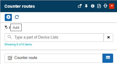
In the administration section of the i4connected portal, click on the Counter Routes tile.
The Counter Routes panel is opened, displaying all the i4connected Counter Routes.
In this view, click on the Add toolbar button.
In the Add list of devices list panel proceed with the following settings:
Type in the Name of the new List of Devices list.
Upload a Photo for the new List of Devices list.
Click the Save bottom button.
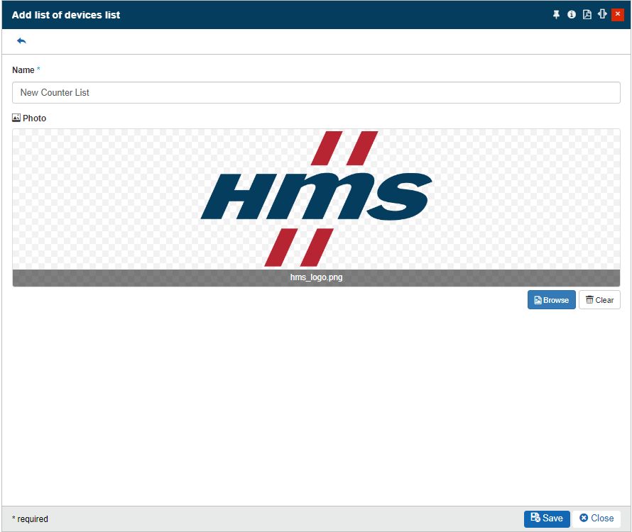
The Add list of devices list panel is closed and the new Counter has been added to the list.
In the Counter routes panel start typing the name of the newly created List of Devices.
The list is filtered to display the searched List of Devices.
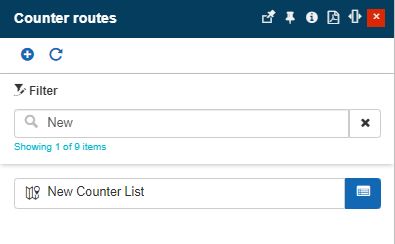
Click on the Edit button to open the List of Devices panel.

Click the Add counter toolbar button.
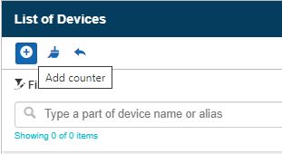
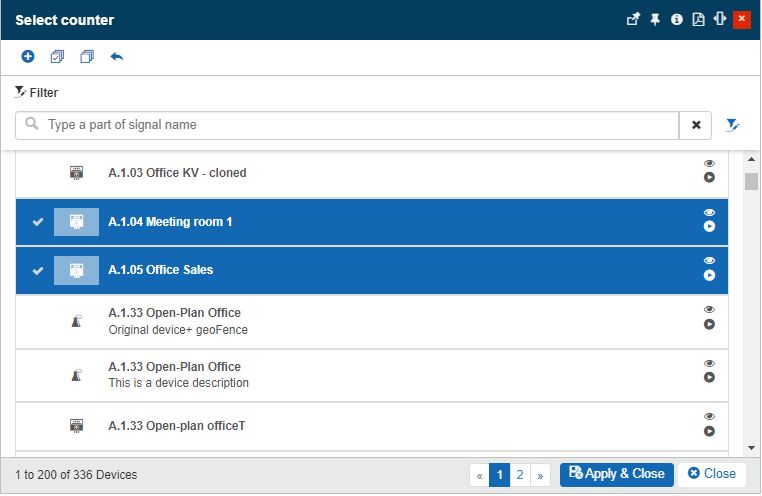
The Select counter panel is opened where all the available Manual Counter Devices are listed.
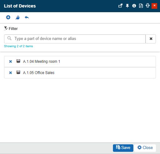
Select the desired Devices and click the bottom Apply & Close button, when ready.
The selected Devices are applied. To confirm the changes click the bottom Save button, of the List of Devices panel.
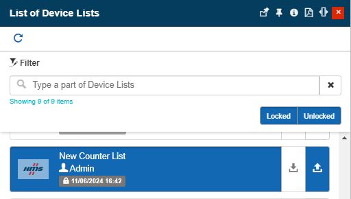
As we now have the new Manual Counter prepared, we can proceed to the Overview section of the portal and click on the List of Devices Lists tile.
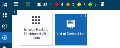
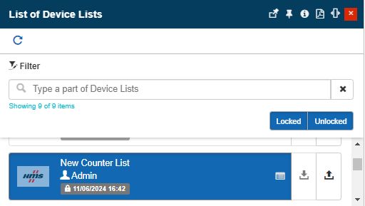
The List of Device Lists panel is opened where all Device Lists are available.
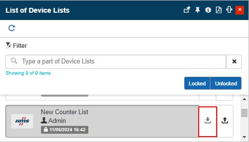
Search for the previously created Counter Route.
The new counter route is in the state of Unlocked. So to proceed with adding values, you need to Lock it using the designated button.
Click on the Device List card to open the Table input.
In the Table Input panel, click on the Signals button to manage values.
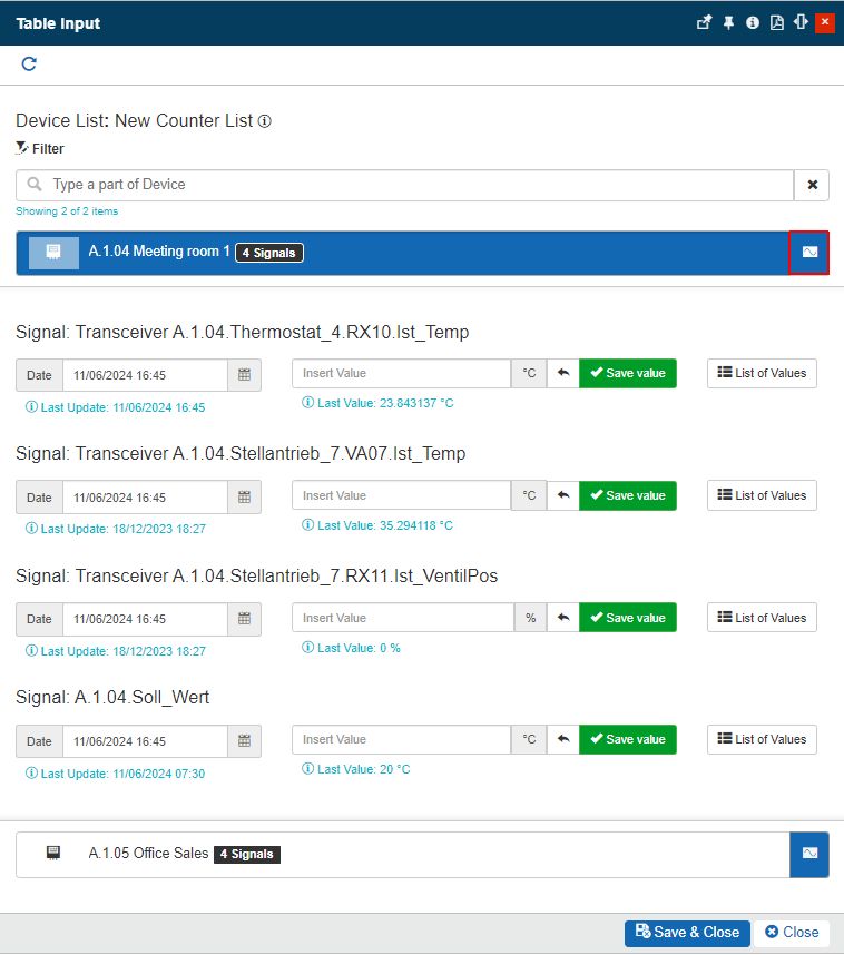
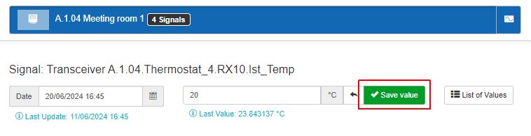
Select the Date, insert the Signal value, and click the Save value button.
A toast message is displayed confirming the success of the write operation.
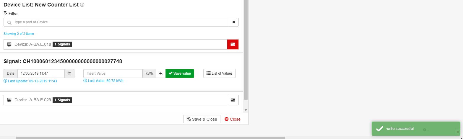
The Signal area is updated and the Info labels display the new value you added. Next, click on the List of Values button.
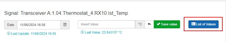
The View Signal panel is opened. In this view, the chart displays the last value you added. The list at the bottom of the chart also displays your value.

Tip
Further values can be added in this view, by clicking the Add signal value button, available at the top of the chart. More details about the View Signal panel can be found in the documentation section.
If no further Signal values are necessary click on the Close bottom button of both the View Signal and Table Input panels. In the List of Devices Lists make sure that you Unlock the previously updated entity, using the designated button.
Defining and using i4scada Adapters
Check out this tutorial and follow the steps to add a new i4scada Device and Adapter and define its Signals and Configured Alarms.
Adding a new i4scada Device and Adapter
In order to configure an i4scada Device and an Adapter in the context of the i4connected platform, please follow the below-described steps:
Go to the i4connected Admin section and click on the Sites tile.
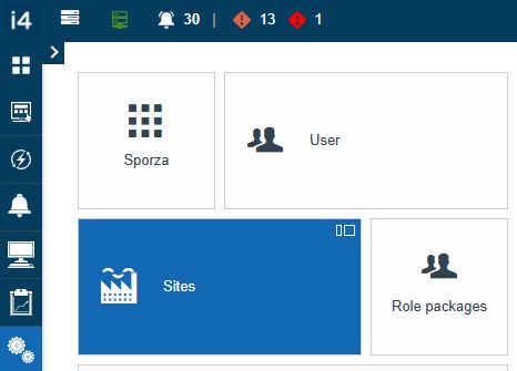
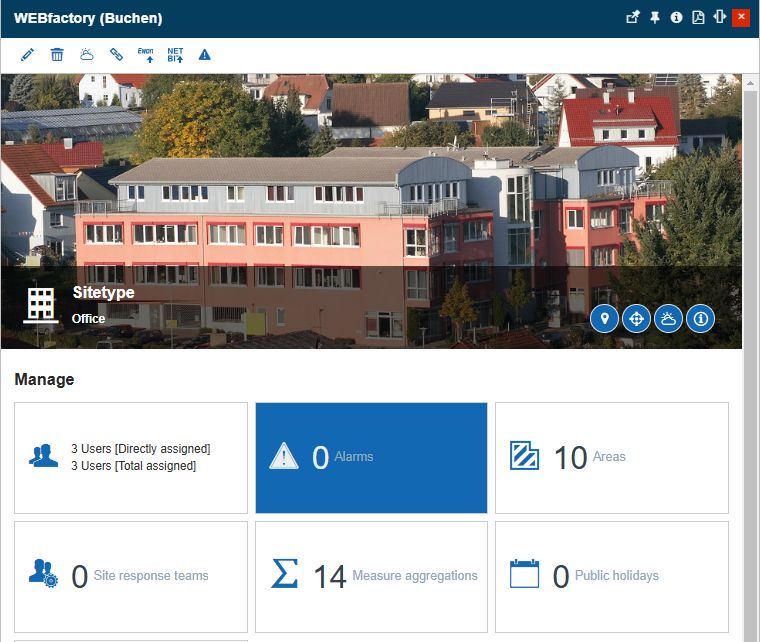
The Sites panel is opened. Select the Site where the new i4scada Device should be added.
In the Site's detailed view mode click on the Devices tile.
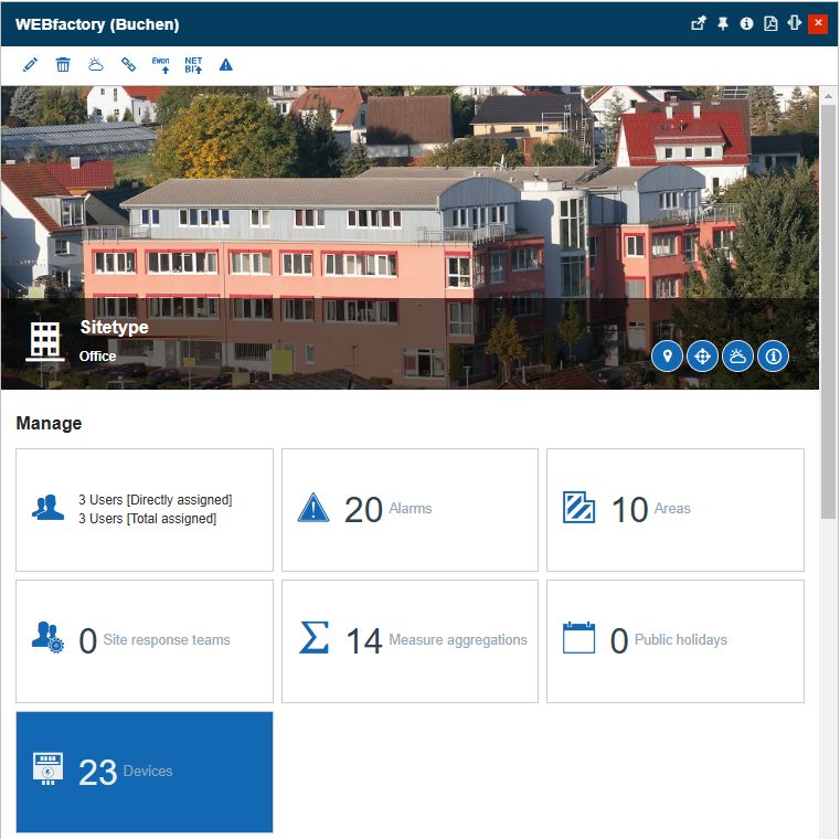
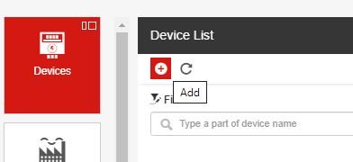
The Device List panel is opened. Click the Add toolbar button.

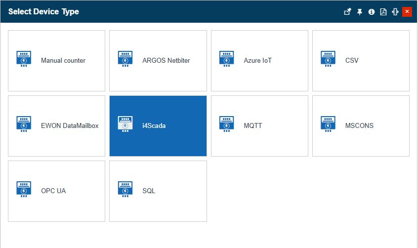
In the Select Device panel, click on the i4scada tile.
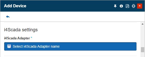
In the Add Device panel, fill in the mandatory information such as Device Name. Fill in all the other needed optional information.
Next, click on the Select i4scada adapter name field.
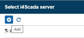
In the Select i4scada server panel click on the Add button.
The Add i4scada Server panel is opened. In this view, fill in the following mandatory settings:
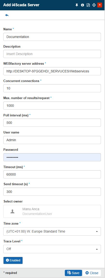
Adapter name
Adapter description
WEBfactory server address
Warning
The SCADA Server should be installed on a machine that is visible for the i4connected server.
Concurrent connections
Max. number of results/request
Poll Interval (max)
User name
Password
Timeout (ms)
Send timeout (s)
Time zone
Trace Level
Set the adapter to status Enabled
Tip
For more details about i4scada Adapters please also visit the dedicated article here.
Click the Save button to preserve the changes.
The Add i4scada Server panel is closed. In the Select i4scada Server panel the newly created server is listed. Select it to add it to your new Device.
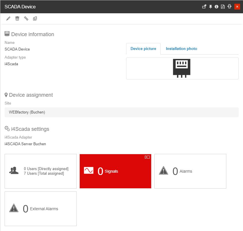
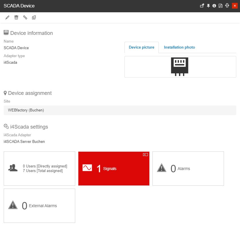
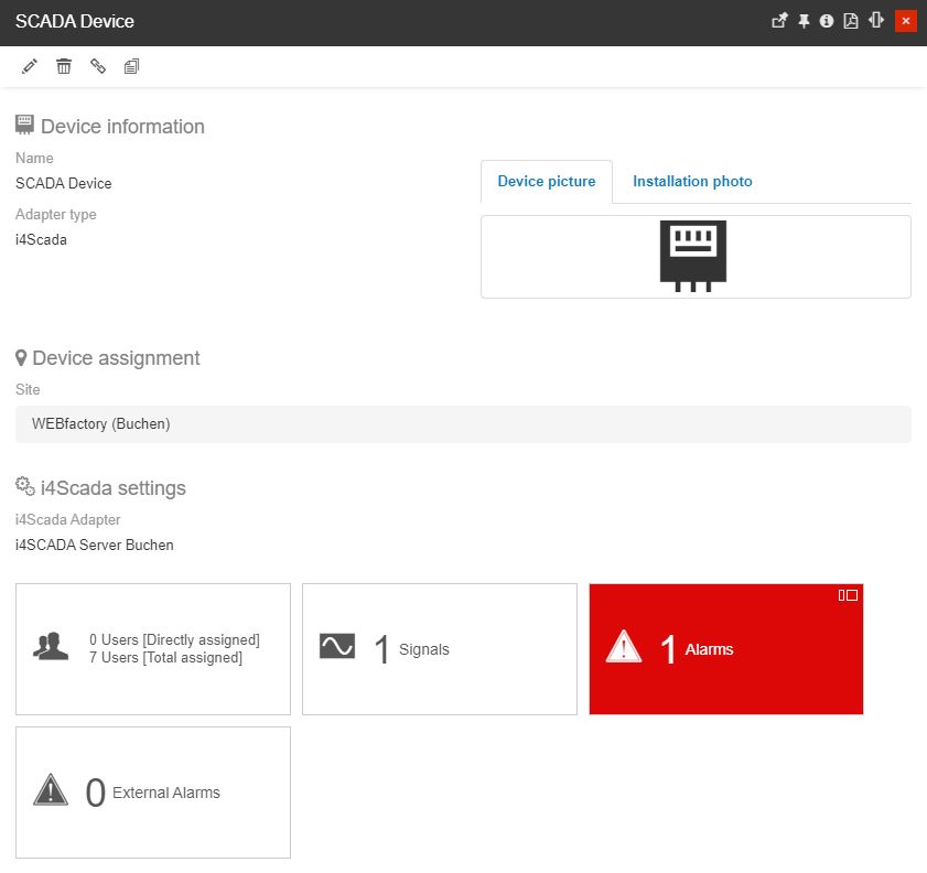
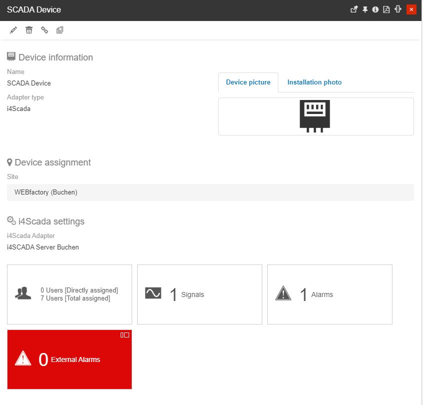
Proceed and save your new i4scada Device. As soon as the new Device is saved, it is opened in detailed view mode.
Notice that the Device has inherited all the parent Site Users, but there are 0 Signals, 0 Alarms, and 0 External Alarms.

Adding new i4scada Signals
To add new Signals to your i4scada Device, proceed as follows:
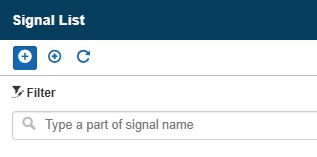
Click on the Signal tile of your Device to open the Signal List panel.
Click on the Add Signal toolbar button.
In the Add signal panel fill in the following settings:
Make sure that the signal is set to Active.
Type in the Signal Name, Alias, and Description.
Leave the Counter settings to their default values.
Click on the Browse i4scada log field to open the list of Signals coming from your SCADA database.
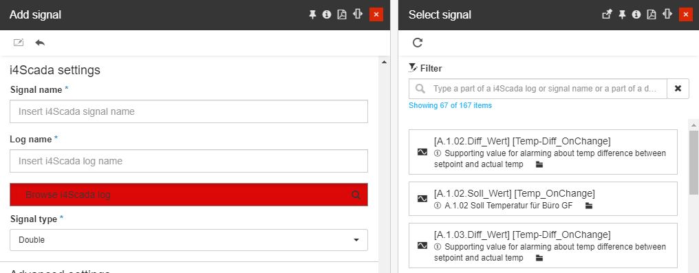
As soon as the desired SCADA Signal was selected, the SCADA Signal name and Log name will be filled in, by the system.
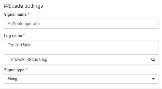
Next, you can select the Signal type choosing from the drop-down list options: Double or String.
Tip
For more details about the i4scada Signal settings, please also visit the dedicated article here.
Proceed with the Advanced settings, as desired.
Set the Signal security as desired.
Click the Save button to add the new Signal to your i4scada Device.
Adding Alarms to an i4scada Device
In order to add new Alarms to your i4scada Device, proceed as follows:
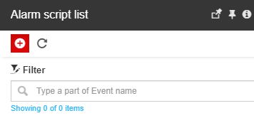
Click on the Alarms tile of your Device to open the Alarm script list panel.
Click on the Add toolbar button.
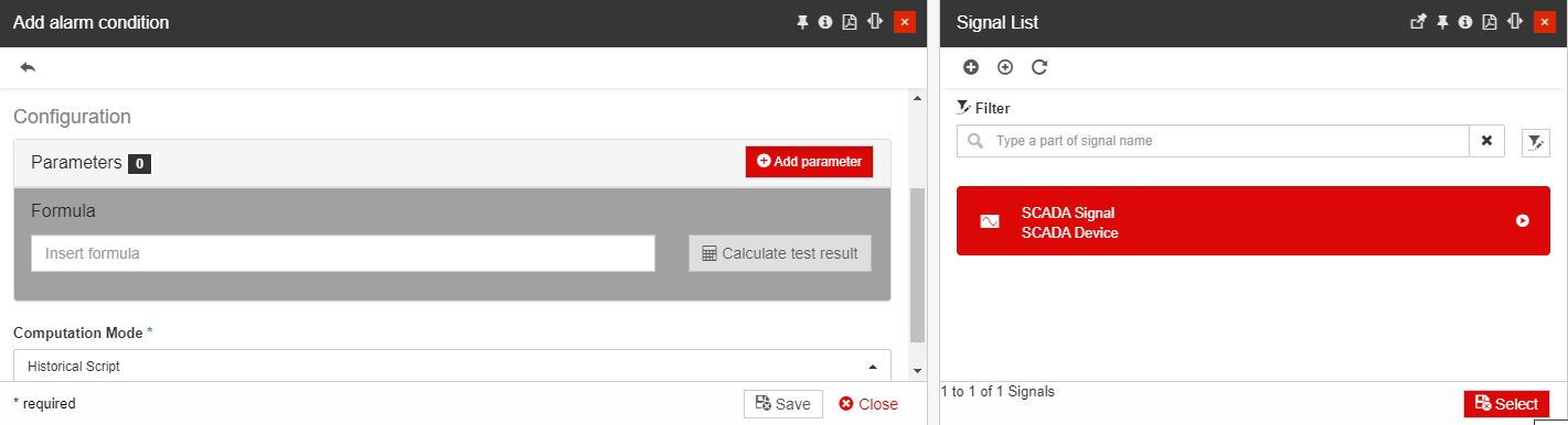
In the Add alarm condition panel proceed with the following settings:
Make sure that the Alarm is set to Active.
Click on the Alarm field to open the list of i4connectedAlarms.
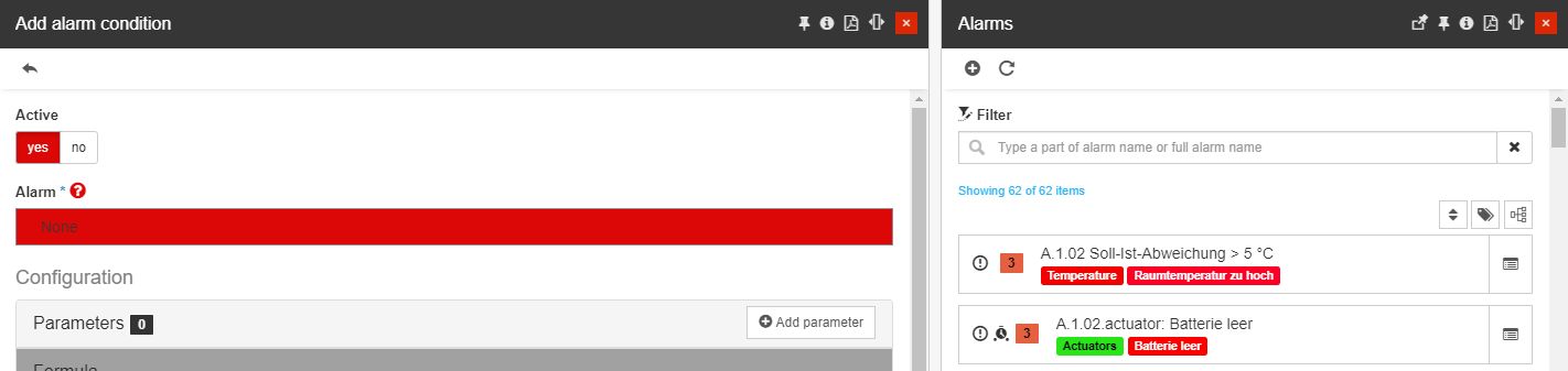
Chose the desired Alarm from the list view.
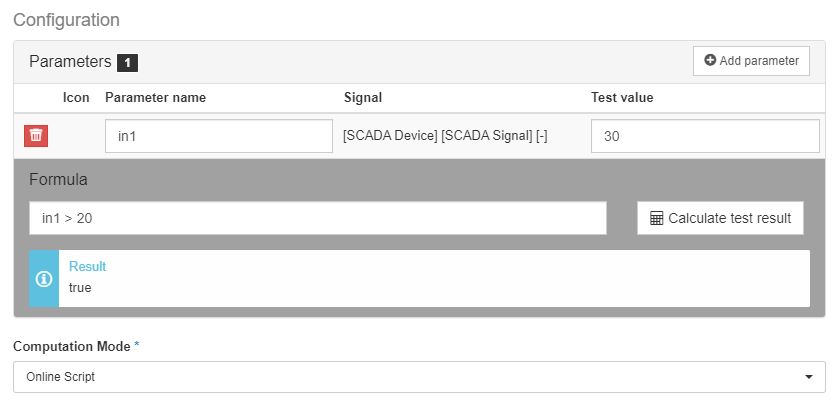
Next, proceed with the Alarm condition configuration, by clicking the Add parameter button.
Select your previously created Signal from the Signal List panel.
As soon as the Signal parameter is added, you can fill in the formula and test the results.
Tip
For more details about the Event script lists, please visit the dedicated article here.
Press the Save button to add the new Alarm to your Device.
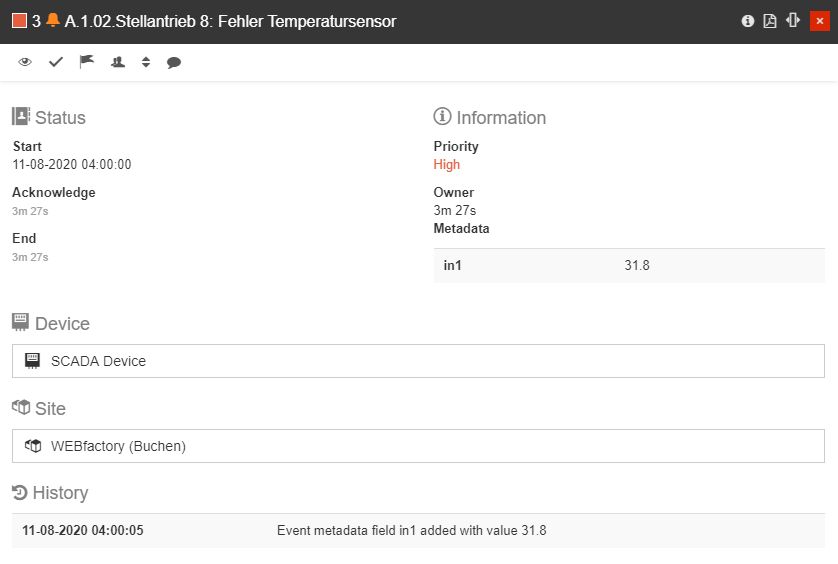
As soon as the Signal value changes, if the inserted condition is not met, a new Alarm will be triggered.
Notice
In our case, the Alarm condition states that the Alarm should be triggered if the registered Signal value is higher than 20. As our Signal returned a value of 31.8 a new alarm was triggered.
Adding External Alarms to an i4scada Device
To add new External Alarms to your i4scada Device, proceed as follows:
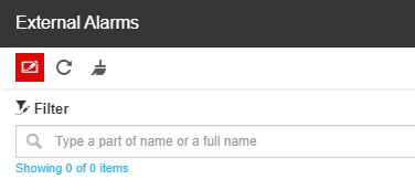
Click on the External Alarms tile of your Device to open the External alarms panel.
Click the Change toolbar button of the External alarms panel.
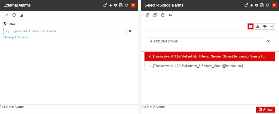
Select the desired External alarm from the Select i4scada alarms panel.
Notice
In this view, all the Alarms coming from your i4scada Server will be listed. This list features a filtering mechanism, allowing you to easily pinpoint the desired alarm, by filtering after Signal, Alarm, Type, and Group.
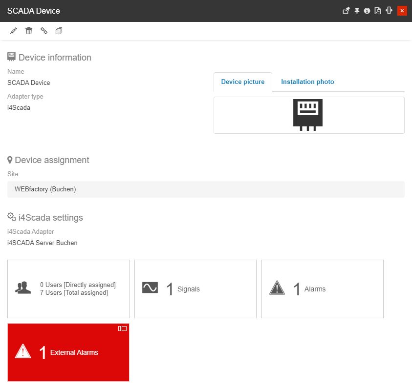
The Device details panel is updated as soon as the Alarm is added.
Using MQTT Adapter to connect Ewon Flexy
Open this article and learn how to use the MQTT Adapter to connect an Ewon Flexy device to the i4connected environment.
The Ewon Flexy is an advanced internet data gateway that allows Machine Builders to monitor and collect vital KPIs for analysis and predictive maintenance from multiple types of PLCs. Using an MQTT Adapter the Ewon Flexy device can be connected to the i4connected platform through an MQTT Broker.
Setup of BASIC IDE in Ewon Flexy
The MQTT functionality of the Ewon Flexy devices is available via BASIC and Java programming environment. As it is easier to access the BASIC programming environment, please follow the below-described steps:
The first step in preparing the Ewon Flexy devices is uploading the CA certificates.
Tip
Depending on the MQTT Broker Certificate type:
If you are using a self-signed certificate on the MQTT Broker, the CA certificate needs to be uploaded to the Ewon Flexy, using an FTP program (e.g. FileZilla). The CA certificate should be uploaded in the user directory via a PEM file format.
On the other hand, if your MQTT Broker uses an official CA certificate, make sure that the name of the MQTT Broker is explicitly assigned in the Alternate Names of the certificate. Wildcard certificates such as *.webfactory-i4.de will NOT work.
Next, you can proceed with installing the BASIC Program on the Ewon Flexy, as follows:
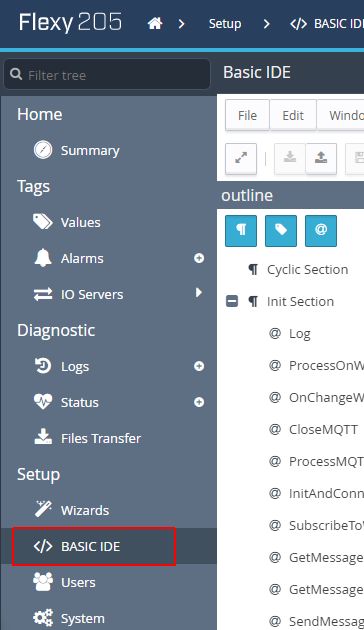
Go to the BASIC IDE menu entry, under the Setup category
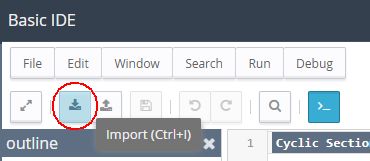
Upload the SendMQTT.bas file into the Init Section by clicking the Import toolbar button. The SendMQTT.bas file can be download here.
Warning
The upload will be possible only if the script execution is NOT in status Running. To stop the scrip execution, toggle the Script execution button.

The Init Section will display the uploaded script. The CONFIG area with the variables is displayed at the top of the script.
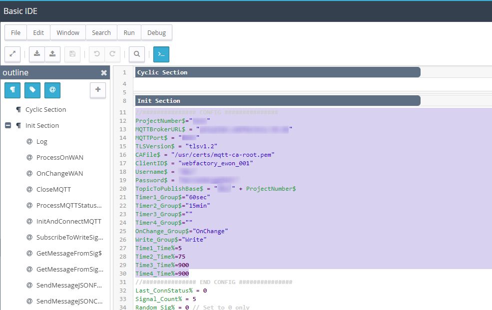
Start configuring the variables to fit your needs. To support you, we prepared a configuration example and some explanations:
Tip
//############### CONFIG ###############
ProjectNumber$="Project1"
MQTTBrokerURL$ = "demo.webfactory-i4.de"
MQTTPort$ = "1883"
TLSVersion$ = "tlsv1.2"
CAFile$ = "/usr/certs/mqtt-ca-root.pem"
ClientID$ = "webfactory_Ewon_001"
Username$ = "webfactory"
Password$ = "Password!"
TopicToPublishBase$ = "webfactory/" + ProjectNumber$
Timer1_Group$="60sec"
Timer2_Group$="15min"
Timer3_Group$=""
Timer4_Group$=""
OnChange_Group$="Alarms"
Write_Group$="Schreiben"
Time1_Time%=60
Time2_Time%=900
Time3_Time%=900
Time4_Time%=900
//############### END CONFIG ###############
As visible in the above example, the topic tree is started using the variables TopicToPublishBase$ and ProjectNumber$ (in this example: webfactory/Project1).
The variables MQTTBrokerURL$ and MQTTPort$ are used to configure the MQTT Broker, whereas the Username$ and Password$ can be extracted from the broker. It is mandatory that the user has permission to write to the topic.
The ClientID$ needs to be unique for each Ewon Flexy device.
Further on, adapt the CAFile$ to correspond to the filename used at step 1, or simply delete or comment the line out by typing // at the beginning of the line.
As we shall see in the upcoming steps, the page names are used to group the tags of the Ewon Flexy, as follows:
Timer1_Group$ - will send data to the JSON format within a 60 seconds interval
Timer2_Group$ - will send data to the JSON format within a 15 minutes interval
OnChange_Group$ - will send data to the JSON format each time the value gets changed
Time1_Time% to Time4_Time% - define the times to send the tags within the defined interval, seconds wise.
For all these pages the topic of the MQTT message is extended by the page name. E.g. in the example above the tags of the page "60sec" are sent to the topic webfactory/Project1/60sec.
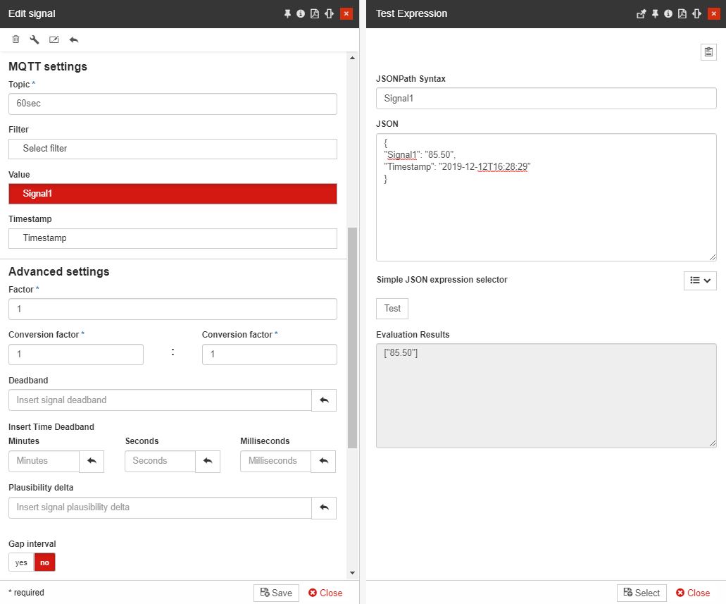
The JSON format is defined like this:
{
"Signal1": "85.50",
"Signal2": "10.29",
"Signal3": "4.80",
"Signal4": "98.04",
"Signal5": "91.77",
"Timestamp": "2019-12-12T16:28:29"
}
The Write_Group$ can be written via publishing an MQTT message, in all the tags on the page. These are transmitted via RAW format, which expects a numerical value (e.g. 10.25). The topic is extended with the page name and the tag name.
For the Write1 tag in the Write page, the following topic will be formed: webfactory/Project1/Write/Write1.
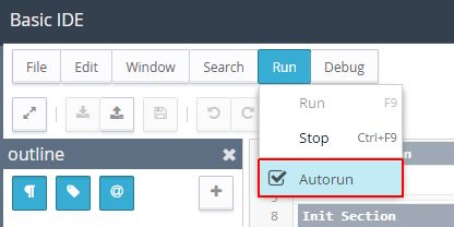
As soon as all the needed variables have been changed, toggle the script execution to RUNNING. If the execution test has passed enable the Autorun option.
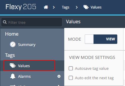
Further on, you need to assign the tags to pages. The tags are managed in the menu Tags under the Values entry.
Note
The tags can be read via the different IO servers or internally (MEM). The exact configuration depends on the used IO server.
Please consider the Ewon Flexy documentation, because this part is out of the scope of this tutorial.
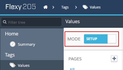
In order to enter in edit mode, toggle the MODE button to change the state from VIEW to SETUP.
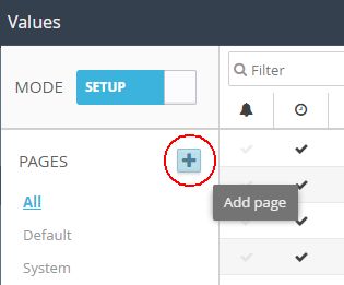
By default, the pages Default and System are available. To add further pages, click on the Plus button.
Proceed with adding the pages as described in step 2d .
Tip
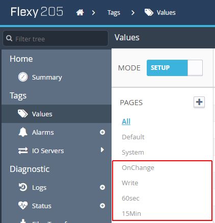
Proposal: add the pages "60sec", "15min", "OnChange" and "Write".
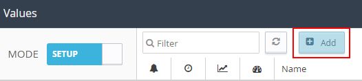
Using the Add toolbar button new Tags can be added.
Further on, by selecting a Tag, the options Edit and Delete are enabled.

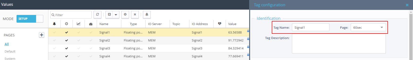
Click the Edit button to open the Tag configuration panel and proceed with the Tag name assignment, to the corresponding Page.
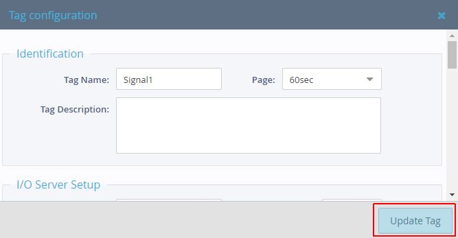
To preserve the changes click the Update Tag button at the bottom of the Tag configuration panel.
Setup of i4connected
After the Ewon Flexy has been organized we need to proceed with the i4connected setup. At the level of i4connected, each MQTT Broker needs one MQTT Adapter for the JSON-Format and one for the RAW format.
The MQTT JSON-format Adapter
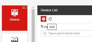
Go to the i4connected Admin page and click on the Devices tile.
In the Device List panel click on the Add toolbar button.
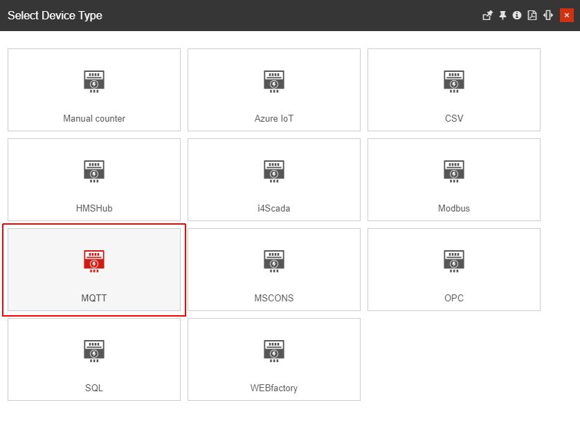
In the Select Device Type panel, click on the MQTT tile.
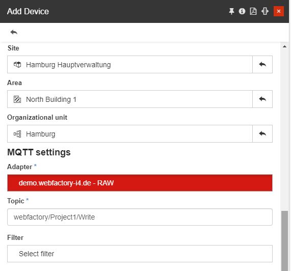
In The Add Device panel, start filling in the Device info:
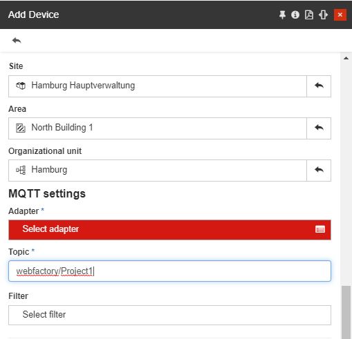
Set the Device Name
Set the Device Site, Area , and Organizational Unit.
Add the Topic extracted from the Ewon Flexy device (for the current example we shall set the topic to webfactory/Project1.
Click on the Select Adapter field to define the JSON format MQTT Adapter:
In the Select MQTT Adapter click on the Add toolbar button.
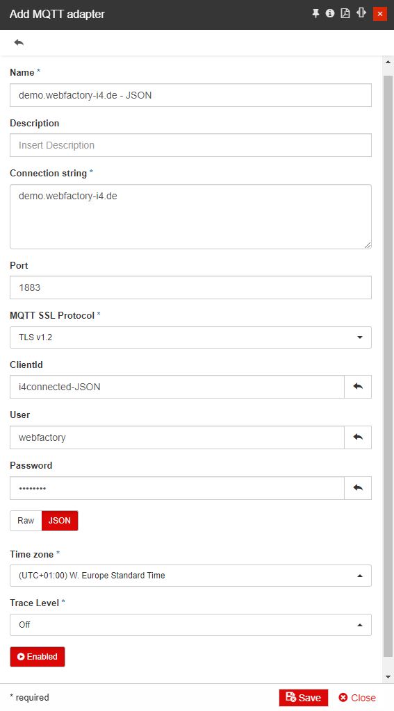
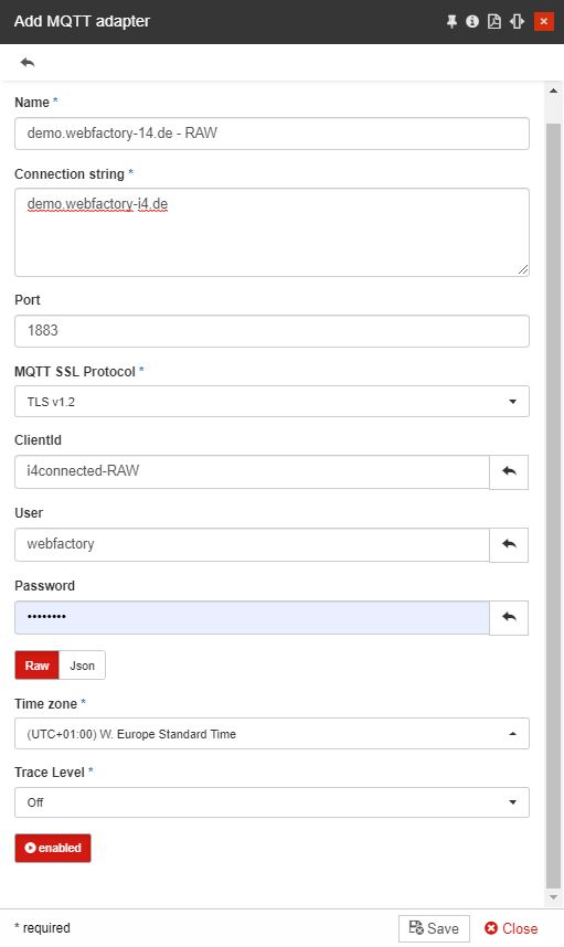
In the Add MQTT Adapter panel start filling in all the required information and make sure that the Adapter is set to JSON format.
Tip
More information about the MQTT Adapter can be found in this article.
Click on the Save button to preserve all the changes made.
After saving the new MQTT JSON-format Adapter, it will be visible in the Select MQTT Adapter panel.
Select the new MQTT Adapter and save the Device.
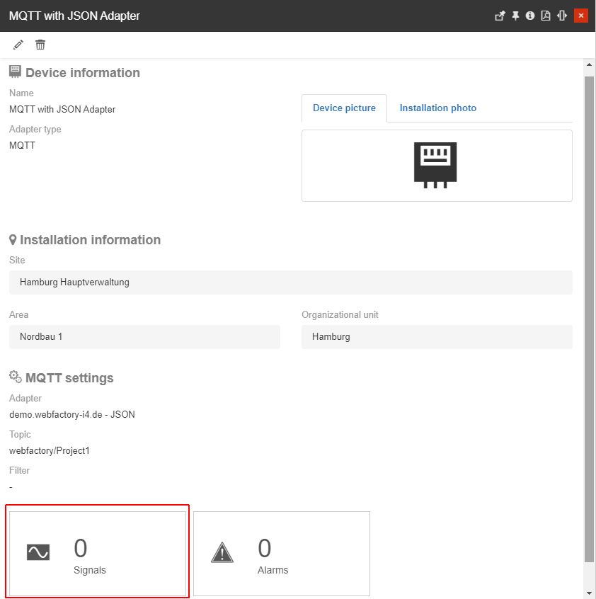
The new MQTT Device with JSON format Adapter is saved and will be opened in detailed view mode.
Click on the Signals tile to proceed with the MQTT Device configuration.
The Signal List panel is opened empty. At this step, our goal is to add new Signals to the Device and connect them to the Ewon Flexy tags.
Type in the Signal Name.
Tip
The i4connected Signal names do not need to be the same as in Ewon Flexy. Any naming can be defined here.
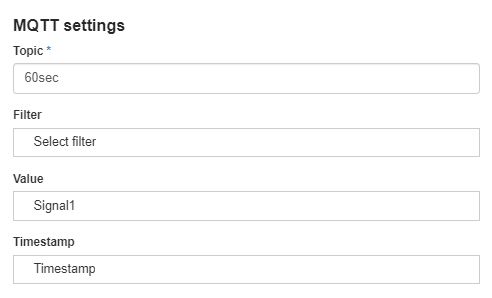
Go to the MQTT Settings and fill in the settings extracting them from Ewon Flexy, as explained in step 2d.
Tip
For more details about the MQTT Signal settings please also visit this article.
Assign the Signal Type as needed.
Topic to the page of the tag in the Ewon Flexy (e.g. 60sec)
Value should be the name of the tag in the Ewon Flexy (e.g. Signal1)
Timestamp should be the Timestamp in the Ewon Flexy (e.g. Timestamp)

Save the Signal and repeat the same steps for all the Ewon Flexy tags, except for the ones on the page Write or the name of the page you set for Write_Group$.
After adding all the needed Signals you can close the MQTT JSON-format Device details panel and proceed with the next steps, described below.
The MQTT RAW-format Adapter
Tip
The RAW format is only necessary if you want to write data back into the Ewon Flexy tags.
Go to the i4connected Admin page and click on the Devices tile.
In the Device List panel click on the Add toolbar button.
In the Select Device Type panel, click on the MQTT tile.
In The Add Device panel, start filling in the Device info:
Set the Device Name
Set the Device Site, Area , and Organizational Unit.
Add the Topic extracted from the Ewon Flexy device (for the current example we shall set the topic to webfactory/Project1/Write.
Click on the Select Adapter field to define the JSON format MQTT Adapter:
In the Select MQTT Adapter click on the Add toolbar button.
In the Add MQTT Adapter panel start filling in all the required information and make sure the Adapter is set to RAW format.
Tip
More information about the MQTT Adapter can be found in this article.
Click on the Save button to preserve all the changes made.
After saving the new MQTT RAW-format Adapter, it will be visible in the Select MQTT Adapter panel.
Select the new MQTT Adapter and save the Device.
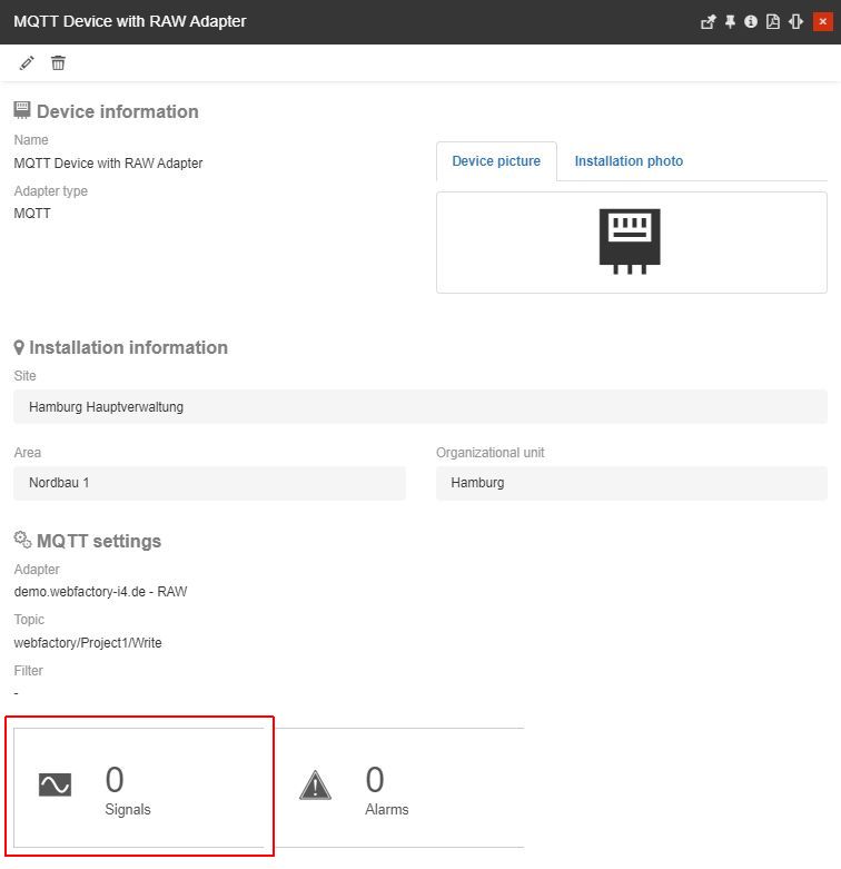
The new MQTT Device with RAW format Adapter is saved and will be opened in detailed view mode.
Click on the Signals tile to proceed with the MQTT Device configuration.
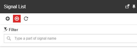
The Signal List panel is opened empty. At this step, our goal is to add new Signals to the Device and connect them to the Ewon Flexy tags.
Type in the Signal Name.
Tip
The i4connected Signal names do not need to be the same as in Ewon Flexy. Any naming can be defined here.
Go to the MQTT Settings and fill in the settings extracting them from Ewon Flexy, as explained in step 2d.
Tip
For more details about the MQTT Signal settings please also visit this article.
Assign the Signal type as needed.
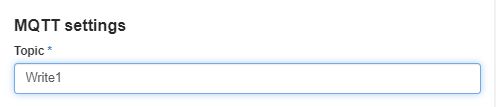
Topic to the name of the tag in the Ewon Flexy (e.g. Write1)
Save the Signal and repeat the same steps for all the remaining Ewon Flexy tags in the Write_Group$ page.
After adding all the needed Signals you can close the MQTT RAW-format Device details panel.
Important
In order to write Signal values, a SCADA page should be integrated into i4connected.
Using the self parameter when working with Virtual signals
Check out this article and learn how you can use the "self" parameter when working with i4connected Virtual Signals.
The "self" parameter is a representation of the current virtual signal, allowing you to access the last value of that virtual signal, without the need to reuse the same virtual signal as an input parameter. By calling it through the script formula, it can supply additional benefits for various use cases.
Open a hierarchical entity in detailed view mode, and access the Devices list.
Select your Device in detailed view mode, and click on the Signals tile.
In the Signals List panel, click the Add virtual signal toolbar button.
In the Add Virtual Signal panel proceed as follows:
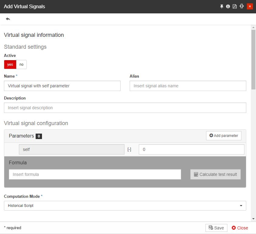
Tip
The "self" parameter is displayed in the Virtual signal configuration section. Since we are in add Virtual signal mode, a real representation of it does not yet exist.
Make sure the virtual signal is Active.
Type in the name of the new virtual signal.
Click the Save button.
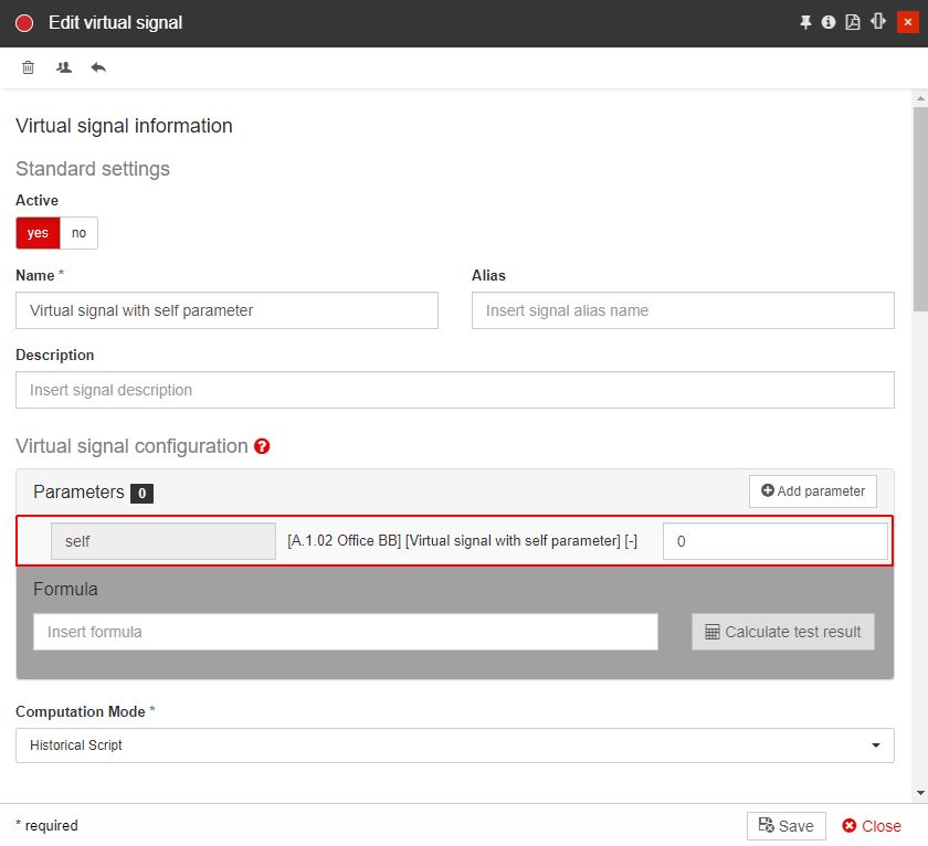
Next, open the previously created Virtual signal in edit mode.
Tip
You will now recognize that the "self" parameter now refers to the current Virtual signal.
With a simple check you can verify if it is returning the expected value:

Add a second parameter, by clicking the Add parameter button, in the Virtual signal configuration section. This will open the list of Signals used by the current Device, allowing you to choose the desired Signal.
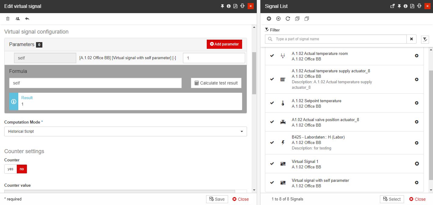
The new parameter is added to the Virtual signal configuration section.
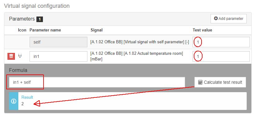
Now, you can proceed with writing the script formula that suits your use case. To verify your formula, click the Calculate test result button. The result will be returned at the bottom of the inserted Formula.
Tip
Even though various use cases can be fulfilled using the "self" parameter, here are some examples:
in1 + self
{
return self + 5;
}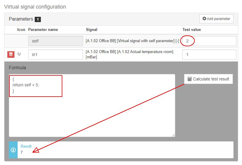
{
return self.Value + in1;
}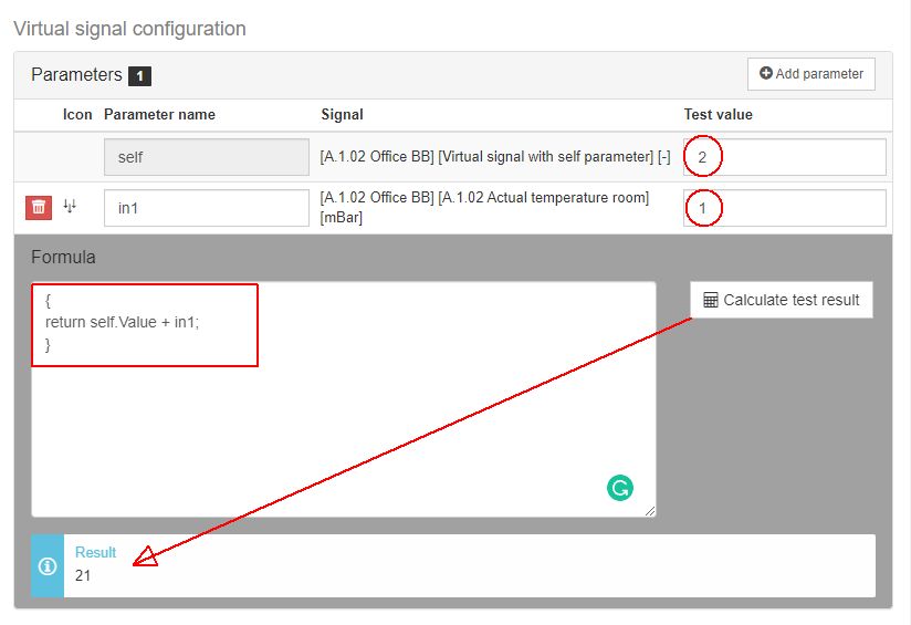
If your script formula is not correct, the system will notify you by posting the "Error compiling script" result.
Make sure to save your changes, by clicking the Save button.