Signals Management
Learn how to manage the i4connected Signals. All that you need to know about adding, editing, deleting Signals, and much other information!
At the level of i4connected, managing Signals can be a complex operation. To provide a simple explanation of the terminology itself, the scope of signals is to identify timestamp associated measurements (data points) registered by a device. The i4connected Signals can establish multiple use cases, depending on the plant needs.
Based on the i4connected signals workflow, there are two separate denominations:
Signal definition - the abstract definition of the signal, consisting of a signal name, description, alias, type, and other advanced settings such as conversion, dead-band, plausibility delta, interpolation, gap, stale data detection, and inactivity intervals.
Signal value (measurement) – the actual manifestation of a signal, consisting of a value/timestamp pair.
The Signal value is involved in consumption measurements since it represents the resulting difference between the last value and the current value (e.g. – an energy consumption counter is read periodically and the measurement is calculated by deducting the current value from the initial value).
Each signal is individually logged. All its measurements are stored in that log and reused for further analysis purposes.
Based on their value-timestamp measurements, we can distinguish two Signal categories:
Counter value Signals – the values registered by a Signal consisting of a value/timestamp pair. These are the actual raw signal values, used in various measurements.
Absolute value Signals – are regular data points that represent various values such as temperature, instant consumption, voltage, etc. Anything that is not a counter falls in this category.
e.g. – the recorded measured values are automatically reused to calculate KPIs.
Signals can be managed in the context of the i4connected Devices, by clicking the Signals tile from the View Device panel, by all users having at least the View sites and View devices permission enabled.
Note
The list of signals will show all the Device's signals and Virtual signals. If a user does not have either the Manage signals or the Manage virtual signals permissions enabled, the listed signals will be displayed as greyed out items.
Opening the Signal List panel
Tip
Check out the Device Management article for more information about i4connected devices.
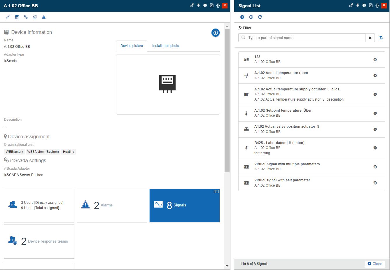
The Signal List panel displays all the Signals assigned to the selected Device, providing the user with the following options:
The Signal List panel
Add signal - opens the Add signal panel.
Add virtual signal -opens the Add virtual signal panel.
Refresh - refreshes the Signal list.
Open Signal in edit mode - opens the Edit Signal panel.
Adding new Signals
Users having the Manage signals permission enabled can click the Add signal button to open the Add Signal panel.
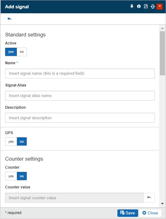
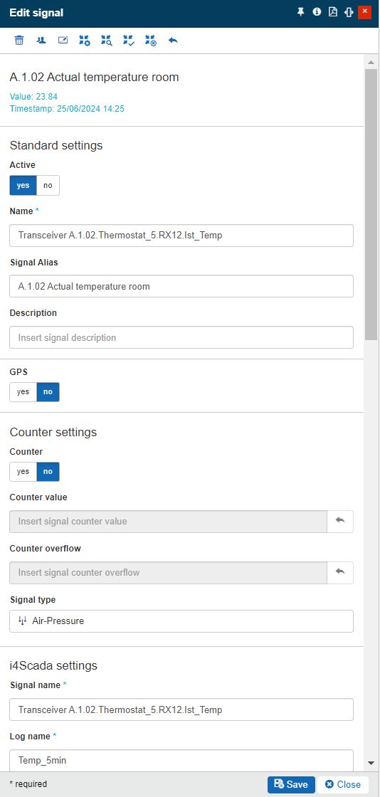
The Add Signal panel
In this view, the user must provide the required (and optional) signal settings and click the Save button to add the signal to the device's signals list. The signal settings are split into the following categories:
Category | Setting | Description |
|---|---|---|
Standard settings | Active | Allows the user to set the Signal as Active or Inactive. When a Signal is deactivated it will no longer write new values. The historical signal values are stored in the system. By creating a new signal, with the same parameters as the inactive one, the historical measurements will be automatically calculated for it and will be able to receive new values, as well. By reactivating the signal it will automatically resume signal writing. |
Name | The PLC name of the signal | |
Alias | The friendly name of the signal | |
Description | The description of the signal | |
GPS | GPS | Enables the Signal as GPS Signal, if the toggle button is set to Yes. TipFor more details about the GPS Signals, please also visit the dedicated article, here. |
Counter settings | Counter | Enables or disables the signal as a counter. |
Counter value | The initial value of the counter. When enabled, the signal is set as a counter signal. | |
Counter overflow | The max value of the counter signal. When the counter reaches this value and starts over, the difference is still calculated correctly. If set to 0, no alarm is raised when reaching the overflow value. | |
Signal type | The type of the signal, defined in the i4connected portal. By clicking this field, the Signal Types panel is opened, allowing the user to select the desired type. Used independently, an i4connected Signal Type is a label providing additional information about a Signal. The Signal Type can be used in a Key Performance Indicator (KPI) formula, hence providing more advanced measurement methods. Signal Types are also involved in i4scada visualizations, providing information for the associated Units of Measure (UoM) giving meaning to the signal. e.g. - Electrical energy, Water, Gas, Heating, etc. | |
Advanced settings | Use Absolute Value | Returns the absolute value of a number. In other words: the Use Absolute Value function removes the minus sign (-) from a negative number, making it positive. |
Factor | The multiplication factor for the signal value. Used to transform the signal value into meaningful analysis value. | |
Conversion factor | Similar to the Factor, the Conversion factor is used to further transform the signal value. The Factor and Conversion factor don't exclude each other. | |
Minimum value / Maximum value | Sets the Min / Max interval for the accepted value updates from the user. ImportantValue updates coming in via the device will ignore this setting. For example, having the Minimum value set to 10 and the Maximum value set to 100, a new value that is lower than 10 and another one, higher than 100, will be rejected. | |
Deadband | The value when the signal is idle. TipFor more details about the Signal Deadband feature, please also visit the article here. | |
Insert Time Deadband | The dead band time is measured in Minutes, Seconds, and Milliseconds. TipFor more details about the Signal Deadband feature, please also visit the article here. | |
Plausibility delta | The maximum difference between two consecutive values for which the values are considered plausible. Exceeding this difference will trigger an alarm. TipFor more details about the Plausibility delta feature, please also visit the article here. | |
Gap interval | The maximum time span between two consecutive values. When this time span is exceeded, an alarm is triggered. If Interpolation is enabled, exceeding this Gap interval triggers the Interpolation. TipFor more details about the Gap detection feature, please also visit the article here. | |
Insert Gap interval | The Gap interval is measured in Days, Hours, and Minutes. TipFor more details about the Gap detection feature, please also visit the article here. | |
Interpolation active | If enabled, the system interpolates the values when a gap is detected between two consecutive values. TipFor more details about the Interpolation feature, please also check the article here. | |
Inactivity Interval | The time interval between two consecutive updates, measured in Days, Hours, and Minutes. The inactivity feature checks if a signal does not write any new values over the defined period of time and triggers an alarm if this happens. The purpose of this setting is to detect broken devices or connectivity issues. TipFor more details about the Inactivity Interval feature, please also check the article here. | |
Stale data detection interval | The time interval between two identical consecutive updates, measured in Days, Hours, and Minutes. The stale data detection feature checks if a counter does not change its value over the defined period of time and triggers an alarm if this happens. The purpose of this setting is to detect broken counters that do not report value changes, therefore it is specific for Signals having the Counter setting enabled. TipFor more details about the State data detection feature, please also check the article here. | |
Measurement handling | Log data points | If enabled, the system logs the signal values, both raw values and end values (after Factor and Conversion factor) |
Stream data points | If enabled, the logged values are streamed through the query engine. | |
Deviation | Is the most significant compression parameter, representing the half-width of the deviation blanket. The deviation blanket is extended between the last recorded value and the new value, with a width equal to twice the compression deviation specification. The Compression Deviation can be expressed as floating-point values, by manual input. | |
Minimum TimeInterval | The compression minimum time has as scope to prevent highly demanding values from using a large amount of archive space. For example, a new log is not recorded if the time since the last recorded event is less than the compression minimum time for the point. The timestamp for minimum compression interval can be defined in minutes, seconds, and milliseconds. | |
Maximum TimeInterval | The compression maximum time is usually set to one value that covers all points in the system. It should be large enough that a point that does not change at all, uses very little archive space. For example, a compression maximum time of one work shift (8 hours) is often a good choice. The timestamp for maximum compression interval can be defined in minutes, seconds, and milliseconds. | |
SCADA Security | Read access | Sets the "Read access" security setting of SCADA Signals, choosing from the drop-down list items: Deny, AllowUnsecured, and AllowSecured. |
Write access | Sets the "Write access" security setting of SCADA Signals, choosing from the drop-down list items: Deny, AllowUnsecured, and AllowSecured. |
Note
The fields marked with bold characters are required in order to add a new signal.
For more details concerning the Device-specific signal settings, please also visit the article here.
Adding new Virtual Signals
A Virtual Signal is a signal that does not receive values from a device but generates them based on a defined formula (or expression). Virtual Signals are defined on the devices just like normal signals but require some additional settings.
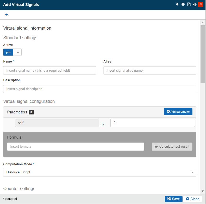
The Add Virtual Signal panel
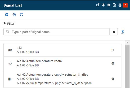
Virtual Signals can be managed by users having the Manage virtual signals permission enabled at the global level.
Warning
Without this permission, the user can only see the Virtual devices in the Signal list panel as grayed-out entities.
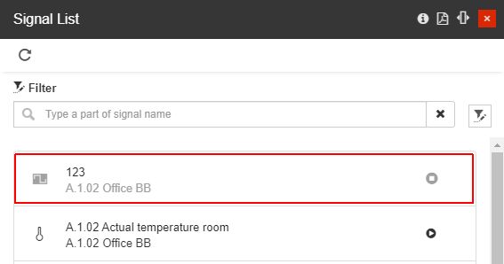
Example of a grayed-out virtual signal
Virtual Signals share most of their properties with the normal signals (see the above table) but they also expose their specific settings.
Category | Setting | Description |
|---|---|---|
Standard settings | Active | Allows the user to set the Signal as Active or Inactive. When a Signal is deactivated it will no longer write new values. The historical signal values are stored in the system. By creating a new signal, with the same parameters as the inactive one, the historical measurements will be automatically calculated for it and will be able to receive new values, as well. By reactivating the signal it will automatically resume signal writing. |
Name | The name of the virtual signal | |
Alias | The friendly name of the virtual signal | |
Description | The description of the virtual signal | |
Virtual signal configuration | Parameters | Allows the user to input signals that can be used in the formula to calculate the expected values. 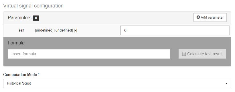 By default, the "self" parameter is available for both new and existing virtual signals, and it is a representation of the current virtual signal. The "self" parameter can be used when writing the script formula in order to access the last value of the Virtual signal. NoteThe "self" parameter can not be removed or renamed, but it will not affect the virtual signal if it is not called by the script formula. To add a new parameter, the user can click the Add parameter button which opens the Signal List panel allowing the user to select a signal to act as input for the formula. The parameters can be either a standard signal or another virtual signal. A virtual signal supports multiple parameters of mixed types (standard signals and virtual signals). ImportantThe parameter names must be unique! Once a parameter is defined, it will be displayed in the table below the Add parameter button. Here the user is able to set the name of the parameter (which will be used inside the formula) and input a test value, allowing the user to test the virtual signal’s formula. 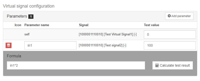 The Parameters area |
Formula | The expression is used to calculate the value of the virtual signal. The expression can use input parameters defined in the Parameters options. The expression can be a simple online calculation or can be a complex, multi-line C# function enclosed in curly brackets {}, in which case a return function is required. The advantage of using complex C# expressions is the availability of variables, loops, etc. Simple expression example: in1 > 10 Multi-line expression example: var calculatedValue = in1 + 10;
if (calculatedValue > 20) {
return true;
} else {
return false;
}When using parameters in your expression, you are not limited only to the value of that parameter. Several properties of the signal used as input parameters can also be used inside the expression:
For example: var signalDelta = in1.Delta;
if (signalDelta > 20) {
return 1;
} else {
return 0;
}Simple expressions using the self parameter: in1 + self or: {
return self + 5;
}or: {
return self.Value + in1;
}The below list illustrates the logical operators that can be used when writing virtual signals expressions:
The value returned by the expression can be of any type, as you can notice in the two examples above. The formula can be tested using the Calculate test result button. This will use the parameter's test value as input value and the result will be listed below. 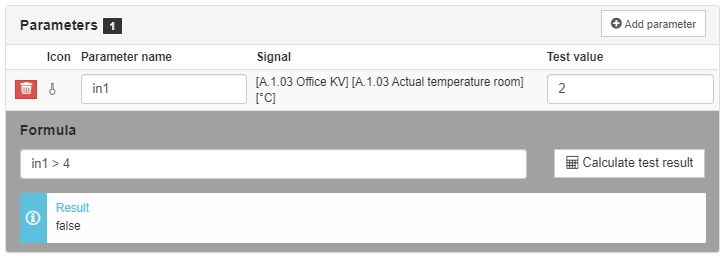 The parameters Formula | |
Computation Mode | The method of using the parameter values.
| |
Counter settings | Counter | Setting this activates the signal as a counter signal. |
Counter value | The initial value of the counter. | |
Counter overflow | The max value of the counter signal. When the counter reaches this value and starts over, the difference is still calculated correctly. If set to 0, no alarm is raised when reaching the overflow value. | |
Signal type | The type of the signal, defined in the i4connected portal. By clicking this field, the Signal Types panel is opened, allowing the user to select the desired type. Used independently, an i4connected Signal Type is a label providing additional information about a Signal. The Signal Type can be used in a Key Performance Indicator (KPI) formula, hence providing more advanced measurement methods. Signal Types are also involved in i4scada visualizations, providing information for the associated Units of Measure (UoM) giving meaning to the signal. e.g. - Electrical energy, Water, Gas, Heating, etc. | |
Advanced settings | Use Absolute Values | Returns the absolute value of a number. In other words: the Use Absolute Value function removes the minus sign (-) from a negative number, making it positive. |
Factor | The multiplication factor for the signal value. Used to transform the signal value into meaningful analysis value. | |
Conversion factor | Similar to the Factor, the Conversion factor is used to further transform the signal value. The Factor and Conversion factor don't exclude each other. | |
Minimum value / maximum value | Sets the Min / Max interval for the accepted value updates. For example, having the Minimum value set to 10 and the Maximum value set to 100, a new value that is lower than 10 and another one, higher than 100, will be rejected. | |
Deadband | Sets the signal variation that will be ignored by the system TipFor more details about the Signal Deadband feature, please also visit the article here. | |
Plausibility delta | The maximum difference between two consecutive values for which the values are considered plausible. Exceeding this difference will trigger an alarm. TipFor more details about the Plausibility delta feature, please also visit the article here. | |
Gap interval | The maximum time span between two consecutive values. When this time span is exceeded, an alarm is triggered. If Interpolation is enabled, exceeding this Gap interval triggers the Interpolation. TipFor more details about the Gap detection feature, please also visit the article here. | |
Insert Gap interval | The Gap interval is measured in Days, Hours, and Minutes. TipFor more details about the Gap detection feature, please also visit the article here. | |
Interpolation active | If enabled, the system interpolates the values when a gap is detected between two consecutive values. TipFor more details about the Interpolation feature, please also check the article here. | |
Insert inactivity interval | The time interval between two identical consecutive updates, measured in Days, Hours, and Minutes. The stale data detection feature checks if a counter does not change its value over the defined period of time and triggers an alarm if this happens. The purpose of this setting is to detect broken devices or connectivity issues. TipFor more details about the Inactivity Interval feature, please also check the article here. | |
Stale data detection interval | The time interval between two identical consecutive updates, measured in Days, Hours, and Minutes. The stale data detection feature checks if a counter does not change its value over the defined period of time and triggers an alarm if this happens. The purpose of this setting is to detect broken counters which do not report value changes, therefore it is specific for Signals having the Counter setting enabled. TipFor more details about the State data detection feature, please also check the article here. | |
Measurement handling | Log data points | If enabled, the system logs the signal values, both raw values and end values (after Factor and Conversion factor) |
Stream data points | If enabled, the logged values are streamed through the query engine. | |
Security | Read access | Sets the "Read access" security setting of SCADA Signals, choosing from the drop-down list items: Deny, AllowUnsecured, and AllowSecured. |
Note
The settings marked with bold characters are required in order to add a new virtual signal.
Adding new GPS Signals
The GPS Signals are used to supply GPS coordinates into the Ewon by HMS Networks system. Based on the provided GPS coordinates, Ewon by HMS Networks operators can track mobile device movements, in order to easily establish when a device exits or enters a target area.
GPS Signals are defined in the context of devices, just like normal signals, but with a slightly different set of properties.
Important
Virtual Signals can not be set as GPS Signals.
Category | Setting | Description |
|---|---|---|
Standard settings | Name | The name of the Signal. |
Alias | The friendly name of the Signal. | |
Description | The description of the Signal. | |
GPS | GPS | Enables the Signal as GPS Signal, if the toggle button is set to Yes. |
Device-specific Signal settings | List of Device specific Signal settings | Based on the Device to which the new GPS Signal is assigned, a set of Device specific Signal settings can be available. TipFor more details, please also visit the dedicated article, here. |
Advanced settings | Insert Time Deadband. | The time Deadband is measured in Minutes, Seconds, and Milliseconds. The purpose of the Time Deadband setting is to insert a minimum interval of time to wait before storing the new values and considering them as updates. All the values that are updated during this interval will be ignored and considered as unnecessary noise. TipFor more details, please also visit the dedicated article, here. |
Security | Read access | Sets the "Read access" security setting of SCADA Signals, choosing from the drop-down list items: Deny, AllowUnsecured, and AllowSecured. |
Write access | Sets the Write access security setting of SCADA Signals, choosing from the drop-down list items: Deny, AllowUnsecured, and AllowSecured. |
Note
The fields marked with bold characters are required in order to add a new GPS Signal.
Editing Signals
Clicking on a signal in the Signal list panel opens the Edit Signal panel allowing the user to edit the signal information (standard settings, device-specific settings as well as parameters, formula, and calculation mode for virtual signals, as described by the previous article.
The Edit signal panel
Besides these settings, while in edit mode, the authorized users are provided with more information about the selected Signal, as follows:
Category | Property | Description |
|---|---|---|
Online value | Timestamp | Displays the date and time of the last registered measurement. 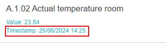 TipThe Online value of a Signal can only be seen by users having at least the Read signals permission enabled. |
Value | Displays the last registered value/counter value. 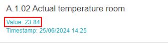 TipThe Online value of a Signal can only be seen by users having at least the Read signals permission enabled. | |
Compression operation status | In preview | Displayed for Signals where compression settings were defined but the actual compression process was not yet applied. 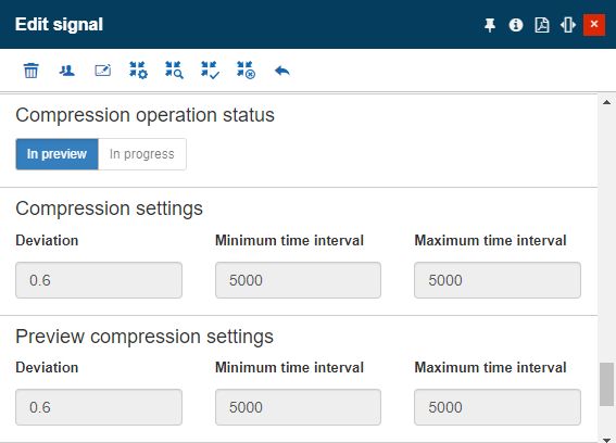 TipFor more details about the Signals compression feature, please read the dedicated article here. |
In progress | Displayed for Signals where compression settings were defined and applied, but are still running in the background. This step might be a long operating task since all the Signal's historical values are compressed. 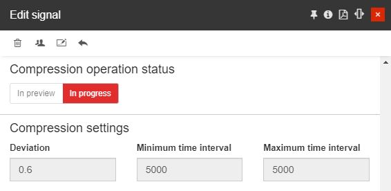 TipFor more details about the Signals compression feature, please read the dedicated article here. |
The Edit signal panel features the User toolbar button which enables the possibility to assign user roles to a Signal.
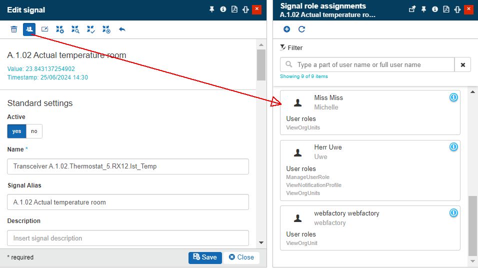
The Signal role assignments panel
Tip
For more details about the Entity role assignments feature, please also visit the dedicated article.
In this view, users having the Write signals permission enabled can process further advanced signal value operations, such as:
Deleting Signals
The toolbar of the Edit signal panel also features the Delete button, allowing users with Write signals permission enabled to remove redundant Signals.
The Delete measurements panel displays a list of consequences involved by the deletion operation (the amount of deleted measurements, events, and signal scripts).
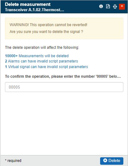
The Delete measurements panel
A confirmation code is requested in this view. In case the typed deletion code is incorrect, the system will warn the user and prevent the deletion operation. After manually typing the correct deletion code and pressing the Delete button, the adapter will be permanently removed.