Device-specific Signal settings
Open this article to learn more details about the Device-specific Signal settings required to configure them by yourself!
Assigning a Signal to some devices requires a set of specific settings.
Azure IoT Hub Signal settings
In order to add a Signal to an Azure IoT Device, the user needs to fill in the following settings:
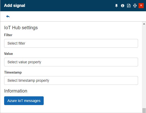
The IoT Hub Signal settings
Filter - opens the Test Expression panel, where the user can fill in the filter JSON property.
Value - opens the Test Expression panel, where the user can fill in the value JSON property.
Timestamp - opens the Test Expression panel, where the user can fill in the timestamp JSON property.
CSV Signal settings
The Signals assigned to a CSV Device require the following specific signals:
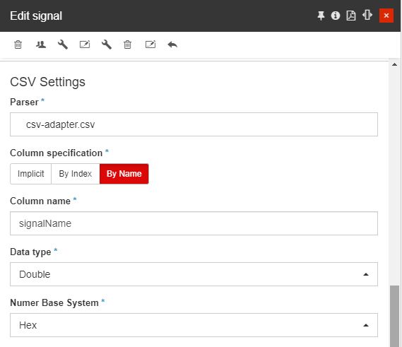
The CVS Signal settings
Parser - opens the CSV parser panel, allowing the user to either select an existing parser or add a new one. By clicking the Add toolbar button opens the Add parser panel.
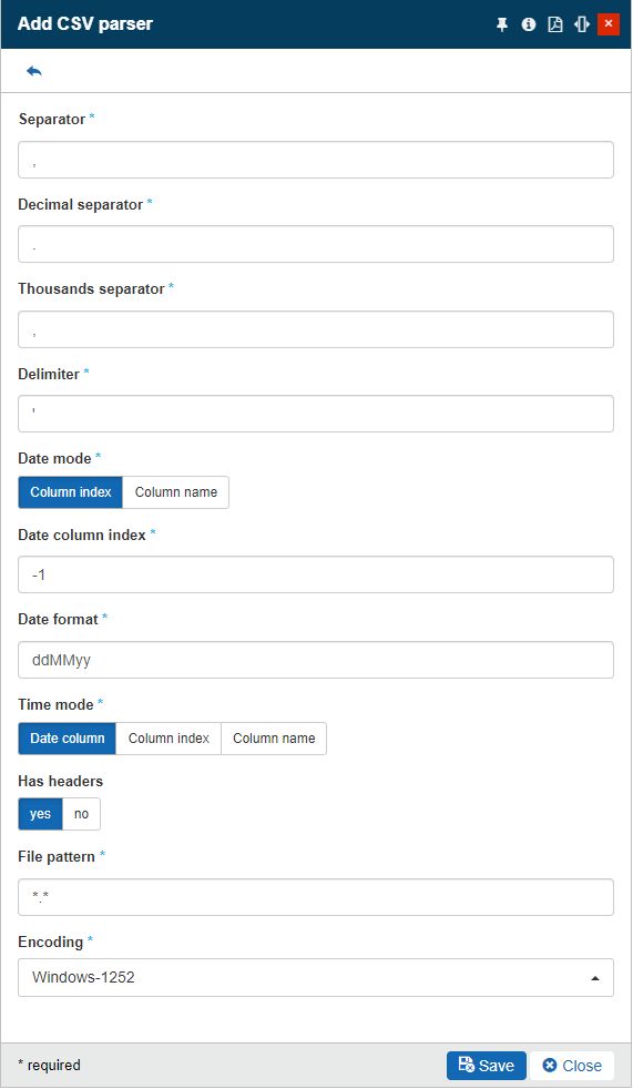
The Add parser panel
In this view the user is required to fill in the following settings:
Separator - by default the comma (,) separator is set.
Decimal separator - by default the dot (.) separator is set.
Thousands separator - by default the comma (,) separator is set.
Delimiter - by default one single apostrophe (') separator is set.
Date mode - allows the user to set the mode to:
Column index - show date column index and date format field
Column name - show column name and date format field.
Date column index - allows the user to set the date column index. Index can be manually typed in the field or by using the up / down arrows.
Date format - allows the user to set the format used for the date.
Time mode - allows the user to set the mode of the time:
Date column - use date column (no time column / format fields)
Column index - show time column index and date format field
Column name - show time column name and date format field
Has headers - allows the user to define if the CSV file will have headers or not.
File pattern - by default the value *.* is set.
Encoding - allows the user to set up the CSV file encoding: Windows-1252, unicode-FFFE, us-ascii, utf-7, utf-8, utf-16, utf-32, utf-32BE.
Column specification - allows the user to set up the column specification, to either:
Implicit - uses the signal name (no input required)
ByIndex - shows column index input (required field)
ByName - shows column name input (required field).
Data type - The signal type: Boolean (only type for Coils and Discrete Inputs), Char, Byte, Int16, Int32, Int64, SByte, UInt16, UInt32, UInt64, Single and Double.
Number Base System - The number base system used by the current signal, allowing the user to choose from the following options:
Hex - hexadecimal base system
Bin - binary base system
Dec - decimal base system
Ewon Signal settings
The Signals assigned to an Ewon Device require the following specific signals:
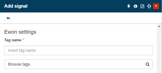
The Ewon Signal settings
Tag name - the name of the Ewon tag, selectable when clicking the Browse tags button.
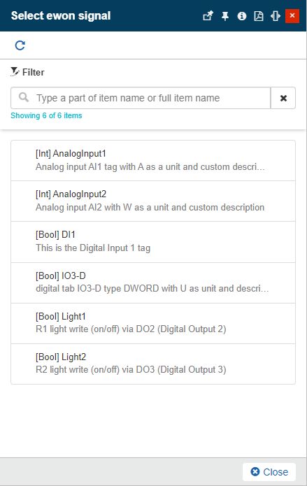
Example of a list of Ewon signals
When manually adding a new signal to your Ewon device, measurements for that signal will be displayed in the Edit signal panel, only after the update cycle has passed.
Tip
When the Ewon signal name ends with “_ctr” (case insensitive), the signal will be imported as a counter in the i4connected system and the counter value will be set to 999999999999, in order to force the first value to be invalid.
Ewon signals values can be written by filling in the Ewon device Username and Password, as described by the Device type dependent settings article.
GridVis Signal settings
The signals defined for a GridVis Device, require the following settings:
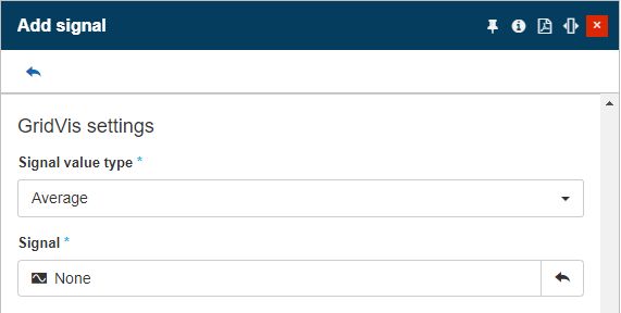
The GridVis Signal settings
GridVis signal value type - allows selection of the signal value type. GridVis Signals can provide 3 value types:
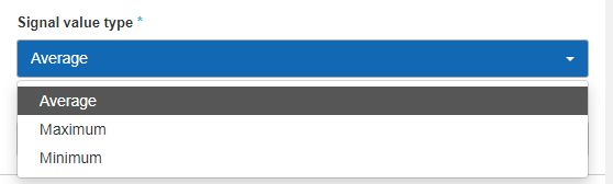
The GridVis Signal value type selector
Avg (Average) - given by a sum of all measurements divided by the number of Signal values.
Max (Maximum) - given by the highest measurements.
Min (Minimum) - given by the lowest measurements.
GridVis signal - allows selection of the GridVis signal. By clicking the selector, the Select GridVis signal panel is opened where all the accessible signals are listed.
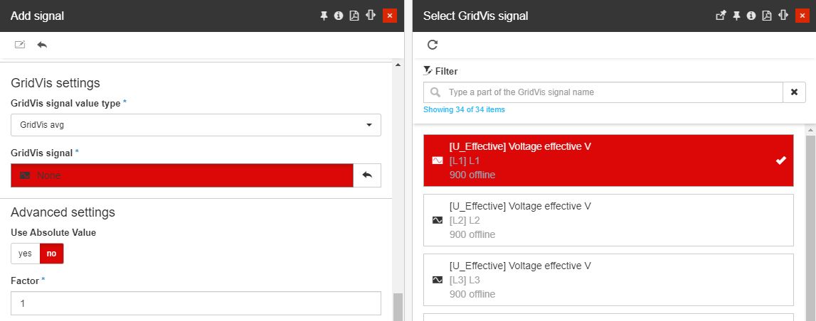
The Select GridVis signals list
When manually adding a new signal to your GridVis device, measurements for that signal will be immediately displayed in the Edit signal panel.
HMSHub Signal settings
The Signals defined for an HMSHub Device, require the following settings:
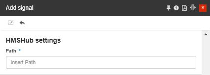
The HMSHub Path
Path - the Endpoint URL establishing the connection to the WEBservice.
i4scada Signal settings
In order to add a new i4scada Signal the user is required to set up the following settings:
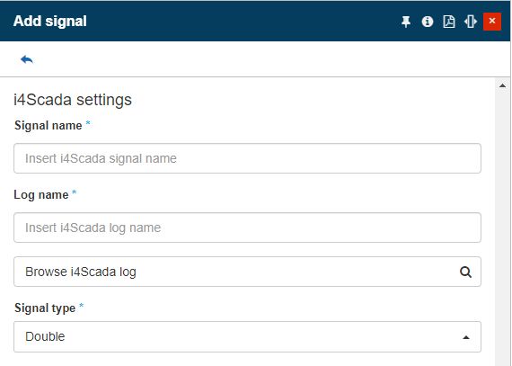
The i4scada Signal settings
Signal name - The name of the i4scada signal.
Log name - The name of the i4scada log associated with the signal.
Browse i4Scada log - allows the user to browse for the i4scada log to be applied.
Signal type - The type of the signal value. Can be:
Double
String
Modbus Signal settings
The Modbus Device specific Signal settings are the following:
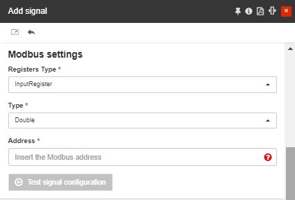
The Modbus Signal settings
Registers Type - The Modbus register type. Can be:
Coil - On/off discrete values that can be read and written Bitwise (bit by bit)
Discrete Input - On/off discrete values that can be only read Bitwise (bit by bit)
Input Register - Numerical values that can be only read Wordwise (word by word)
Holding Register - Numerical values that can be read and written Wordwise (word by word)
Type - The type of data of the signal. Can be: Boolean (only type for Coils and Discrete Inputs), Char, Byte, Int16, Int32, Int64, SByte, UInt16, UInt32, UInt64, Single, and Double.
Address - The address of the signal, which depends on the register type.
Coils addresses start with a zero and then span from 00001to 09999
Discrete Input addresses start with a one and then span from 10001 to 19999
Input Register addresses start with a three and then span from 30001 to 39999
Holding Register addresses start with a four and then span from 40001 to 49999
Test signal configuration - allows the user to test the signal configuration.
MQTT Signal settings
In order to add a new MQTT Signal, the user is required to fill in the following settings:
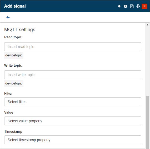
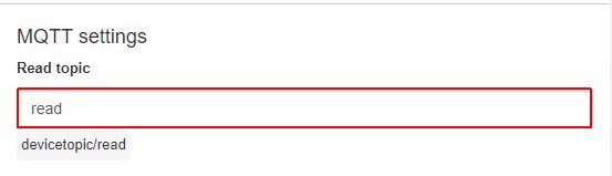
Read topic - allows the user to set the name of the MQTT signal read topic. The Read topic of the signal will be automatically concatenated with the parent device topic.
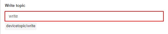
Write topic - the name of the Write topic associated with the MQTT broker. This field is only available when the JSON property is selected under the MQTT adapter. The Write topic of the signal will be automatically concatenated with the parent device topic.
Filter - opens the Test Expression panel, where the user can fill in the value in the JSON property. This field will only be displayed for signals having a parent device using a JSON type MQTT adapter.
Value - opens the Test Expression panel, where the user can fill in the value in the JSON property. This field will only be displayed for signals having a parent device using a JSON type MQTT adapter.
Timestamp - opens the Test Expression panel, where the user can fill in the value in the JSON property. This field will only be displayed for signals having a parent device using a JSON type MQTT adapter.
MSCons Signal settings
The MSCons Device settings required to Add a new Sign are:
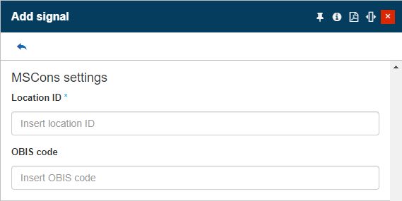
The Add MSCons signal panel
Location ID - the identification number of the device location.
OBIS code - the corresponding device value.
Netbiter Signal settings
The Signals assigned to a Netbiter Device are selected by clicking the Browse netbiter parameters selector.
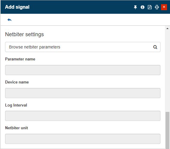
The Add Netbiter signal panel
In this view, the user can choose the desired Netbiter signal, belonging to the Netbiter adapter. The Netbiter signals are displayed as cards in a scrollable list view. Each signal card displays the Signal name, Log interval, and the used Unit of measure.
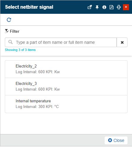
The list of Netbiter signals
As soon as the Netbiter signal is selected, the read-only parameters are prefilled with data, as follows:
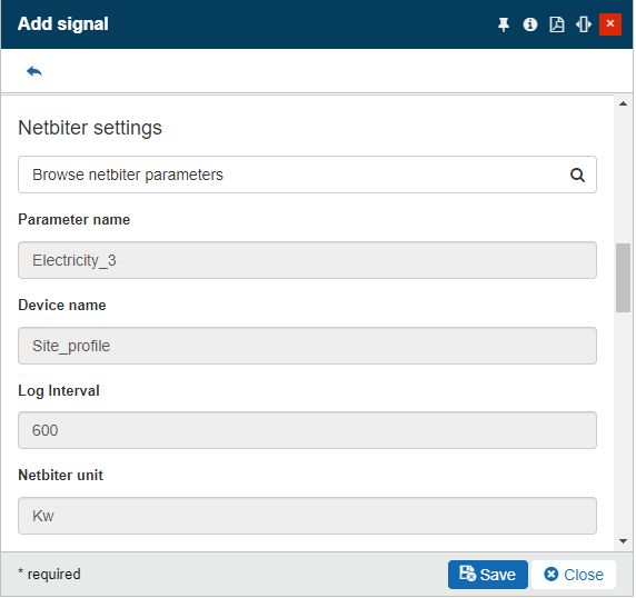
The Netbiter signal parameters
Parameter name - the name of the Netbiter signal.
Device name - the name of the Netbiter source device.
Log interval - the logging interval applied for the Netbiter signal.
Unit - the unit of measure associated with the Netbiter signal.
Note
The measurements of Netbiter Signals that have been manually added to i4connected system are delayed, as they depend on several factors:
The Device Polling interval
The Signal Log interval
For example, a Netbiter Device will check for new values within a polling interval of 15 minutes. Depending on the Signal Log interval, new values will be written in i4connected only after the entire logging and polling cycle has ended.
Tip
When the Netbiter signal name ends with “_ctr” (case insensitive), the signal will be imported as a counter in the i4connected system, and the counter value will be set to 999999999999, in order to force the first value to be invalid.
OPC UA Signal settings
The Signals assigned to an OPC UA Device are selected by clicking the Browse OPC UA item.
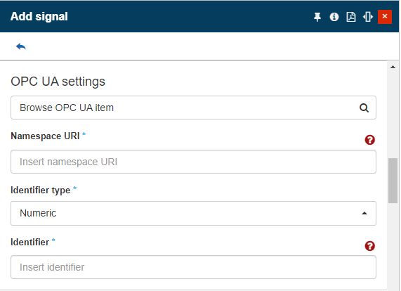
The Add OPC UA signal panel
In this view, the user can choose the desired OPC UA signal, belonging to the OPC UA adapter.
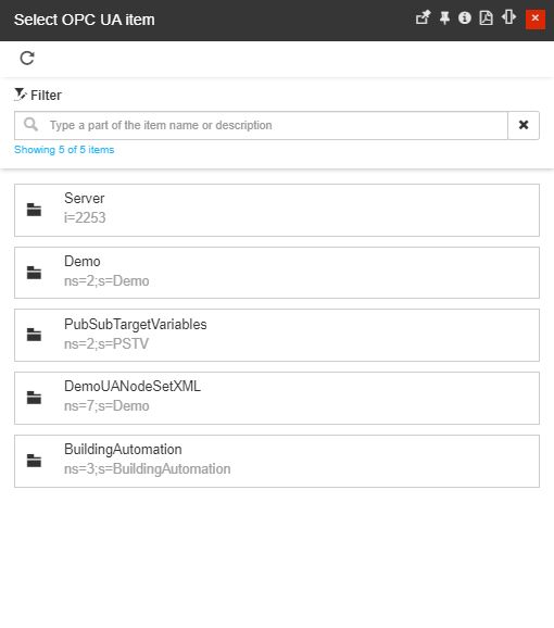
The list of OPC UA signals
As soon as the OPC UA signal is selected, the parameters are prefilled with data, as follows:
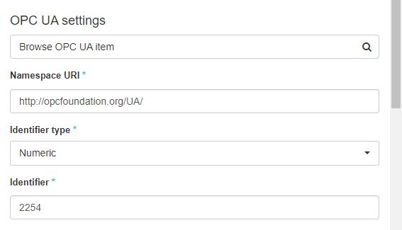
The OPC UA signal parameters
Namespace uri - the signal's namespace, generated on basis of a unique OPC UA identifier.
Identifier type - the type of the signal's identifier as used in the OPC UA server. At the level of i4connected, the drop-down list provides four Identifier types: Numeric, String, Guid, and Opaque.
Identifier - the signal's identifier as used in the OPC UA server.
WEBfactory Signal settings
In order to add a new WEBfactory Signal, the user is required to fill in the following settings:
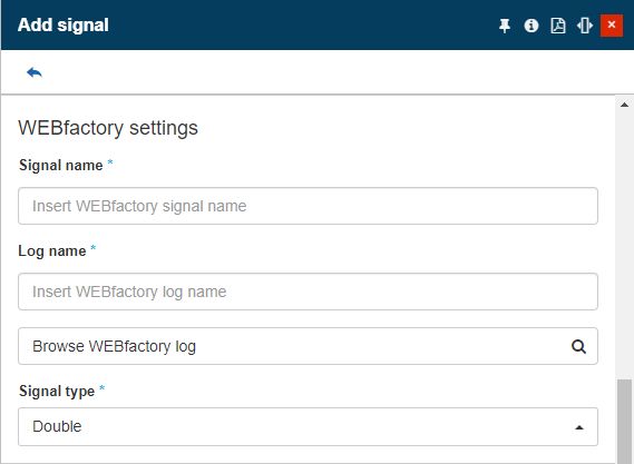
The WEBfactory Signal settings
Signal name - The name of the WEBfactory signal
Log name - The name of the WEBfactory log associated with the signal
Browse WEBfactory log - allows the user to browse for the WEBfactory log to be applied.
Signal type - The type of signal value. Can be:
Double
String