Device details
Check out this article and learn more details about how to edit and manage your i4connected devices, by reading the sub-sections carefully written for you.
The Device details panel is opened by clicking a device card inside the Device List or by adding a new device. This panel displays all the available information about a device and allows the user to perform device-related operations.
Note
The Device details panel will be displayed only for users having the Manage devices permission enabled.
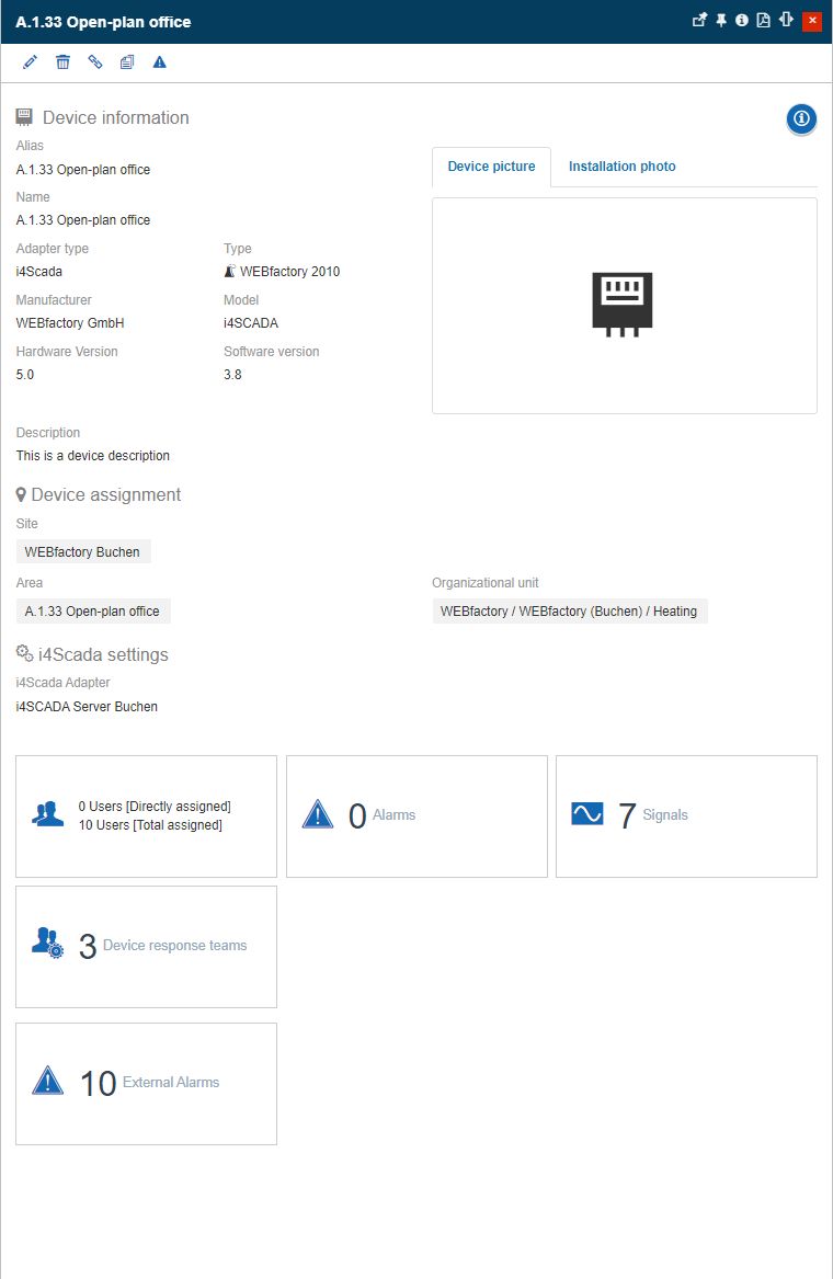
The Device Details panel
The top menu buttons provide access to:
the Edit device panel, where the user can edit the device's settings
the Delete device panel, where the user can delete the device
the Manage application panel, where the user can set up an application mapping for the device
the Clone device panel, where the user can clone the selected device along with all its assignments
the Publish manual events panel, where the user can trigger an alarm, based on a manual event, in the context of the currently selected device.
The main body of the Device Details panel lists the following data:
Device information - the name, type, and other relevant device information;
Installation information - the site, area, and organizational unit where the device is installed;
Device settings - the device type-specific settings configured when the device was created/edited.
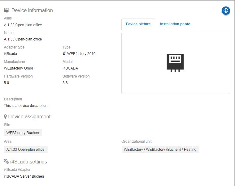
The Device information area
The Alarm suppression button  is displayed at the right top side of the Device details panel, for all the Devices having their Alarms suppressed. By clicking the Alarm suppression button, the Device details panel is expanded to display information about the Alarm suppression mode (Manual or Scheduled).
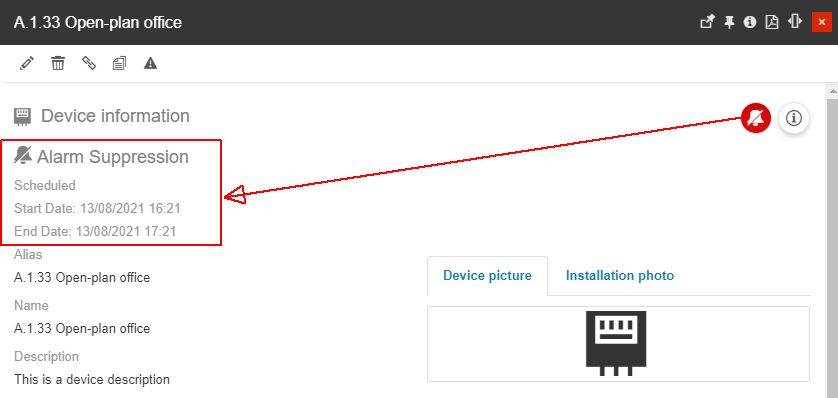
The Alarm suppression information area
Further on, by clicking the Extra information meta toolbar button, the Device detailed view mode panel is expanded to display all the predefined metadata.
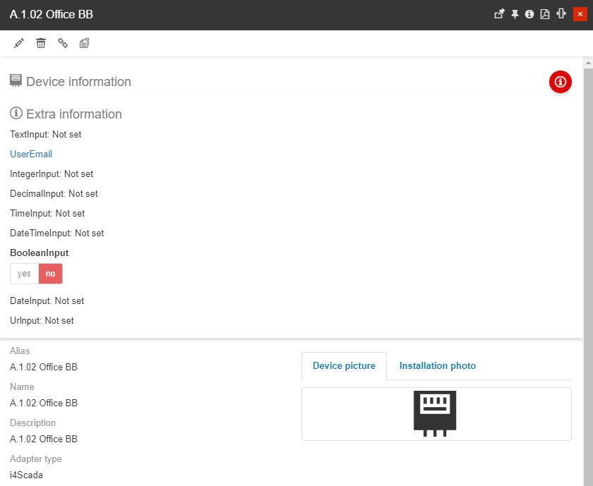
The Device Extra information area
The Extra information area lists all the Device-specific Custom field definitions, in view mode only. However, there is some metadata that allows the user interaction, as follows:
when clicking the linkable field of the metadata of type Url, the URL address is opened in a new tab of the used browser.
when clicking the linkable field of the metadata of type Email, the default email application is opened, having the user's email address prefilled, in the "To" field.
The Device details panel also provides access to the device's users, signals and alarms, through the dedicated tiles. These tiles display the number of users, signals, and alarms assigned to the current device, allowing the user to manage them as follows:
Clicking the Users tile opens the Device role assignments panel, where all the assigned users and their roles are listed.
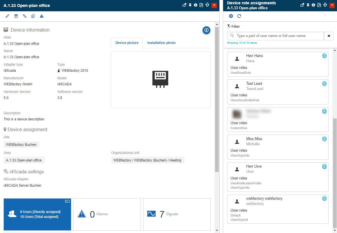
The Device role assignments panel
Tip
Check out the Device role assignments article for more information.
Clicking the Signals tile, opens the Signal List panel, allowing the user to manage the device's signals.
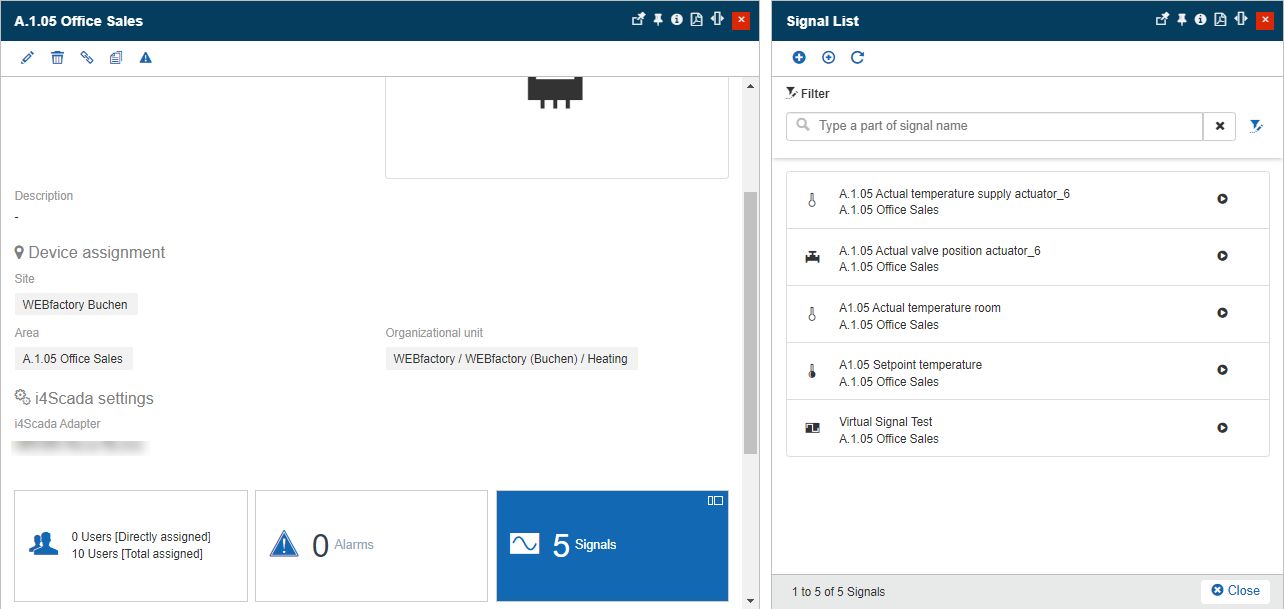
The list of Device's Signals
Tip
Check out the Signals Management article for more information.
Clicking the Alarms tile, opens the Event scripts list panel, allowing the user to manage the device's alarms.
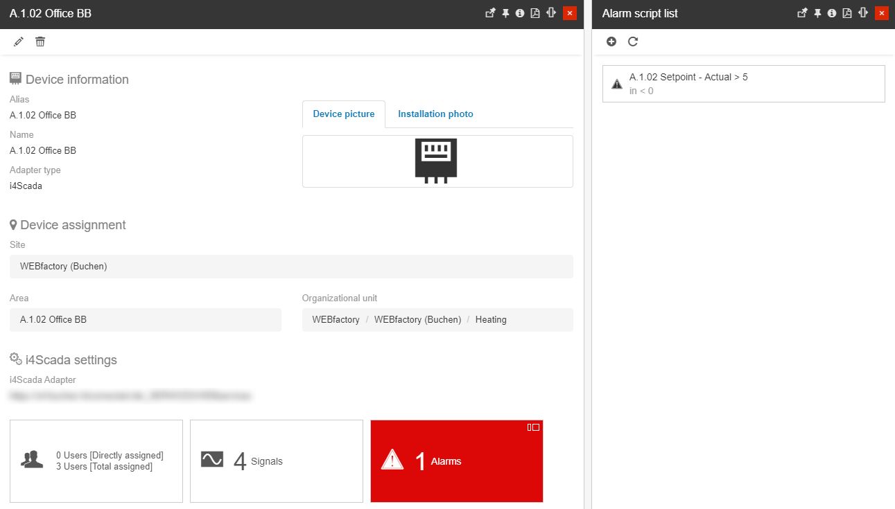
The list of Device's Alarms
Tip
Check out the Event script list article for more information.
Clicking the Device response teams tile, opens the Device Response Team List panel, allowing the user to manage the device's response teams.
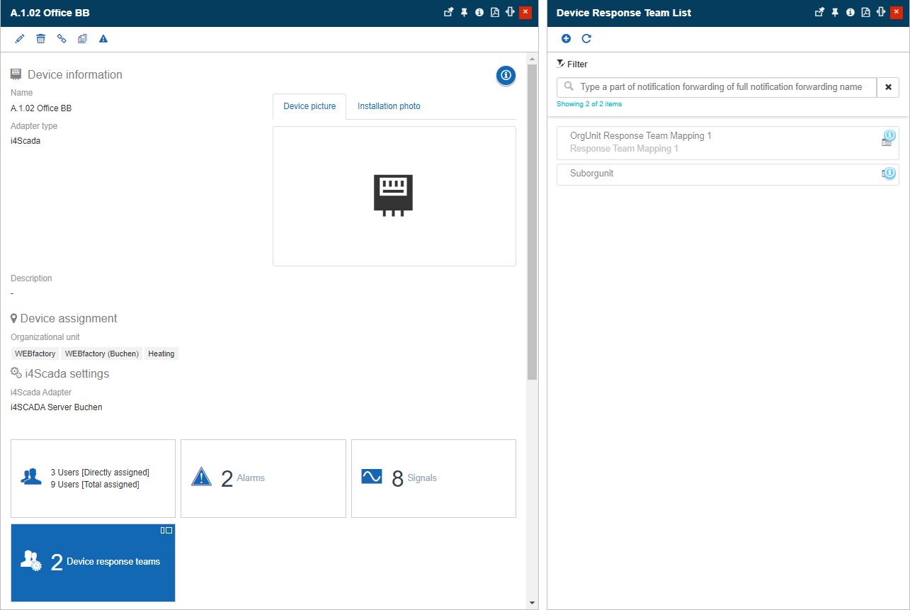
The Device Response Teams List
Tip
Check out the Device Response Team Mapping article for more information.
Clicking the Device Map tile, opens the Device Map panel, allowing the user to view information about the Device's Geofences.
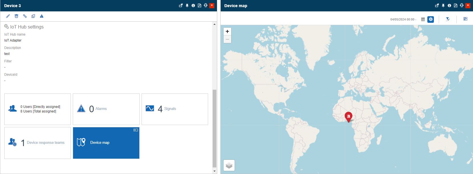
The Device Map panel
Tip
Check out the Device Map article for more information.
If an Application mapping has been assigned to a Device, the details panel also displays a preview of that i4designer visualization.
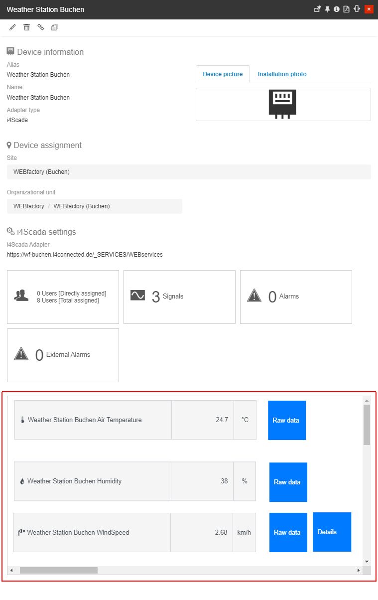
Example of Device application
Tip
For more details about the i4designer Application mapping feature please also refer to the dedicated articles here.
Additionally, to learn how to manage a Device's Application mappings please also visit this article.
Editing Devices
Clicking the Edit toolbar button from the View Device top menu opens the Edit Device panel.
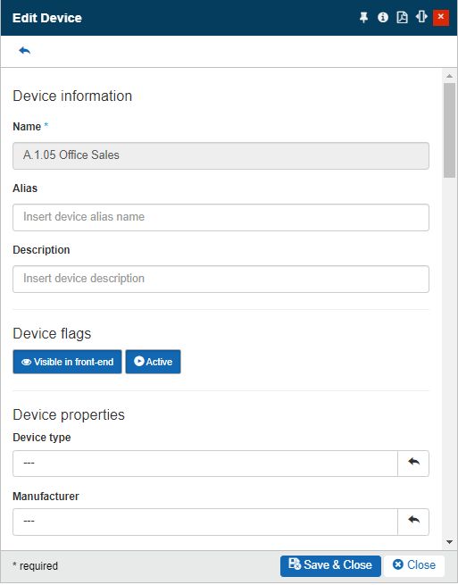
The Edit Device panel
Besides the possibility to edit both the standard device information, as well as the type-dependent information, the Edit Device panel, also features the GPS Tracking Fields button, allowing users to track mobile devices movements.
Tip
Mobile devices are those devices that can change their location, such as mobile generators, mobile pumps, silos, etc.
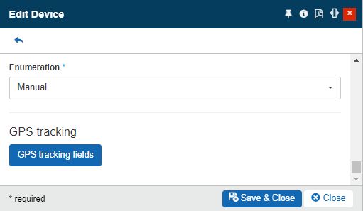
The GPS Tracking Fields button
As soon as the GPS Tracking Fields button is clicked, the GPS Tracking Panel is opened.
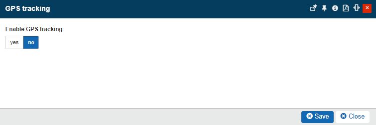
The GPS Tracking Panel
In this view, the user can Enable the Device GPS Tracking by toggling the button to option Yes and filling in the following settings, in order to supply the GPS coordinates of the Device:
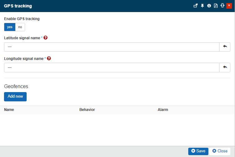
The GPS Tracking settings
Longitude Signal Name - sets the longitude, used to supply the Device's GPS location. The Longitude Signal Name selector opens the Signal List panel, populated with all the GPS Signals, available for the current Device.

Latitude Signal Name - sets the latitude, used to supply the Device's GPS location. The Latitude Signal Name selector opens the Signal List panel, populated with all the GPS Signals, available for the current Device.

Warning
The GPS coordinates are supplied via GPS Signals. Hence, the Device should have at least one GPS Signal. For more details about GPS Signals, please also visit the dedicated article, here.
In case no GPS Signals are available for the currently selected Device, the Signal List panel will be empty.
To finish up the Device GPS tracking, the user can also add Geofences, by clicking the Add new button, in the GPS Tracking panel.
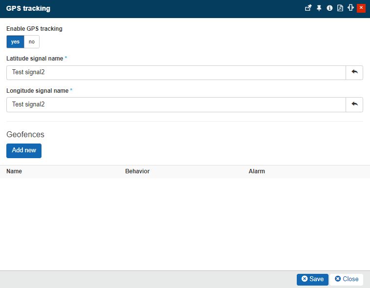
The Add new Geofences button
Tip
A Geofence is a virtual parameter for a real-world geographic area. The purpose of Geofences is to act as a trigger, that can either raise an event (trigger) or close an event (suppress).
The Add Geofence panel features the following properties:
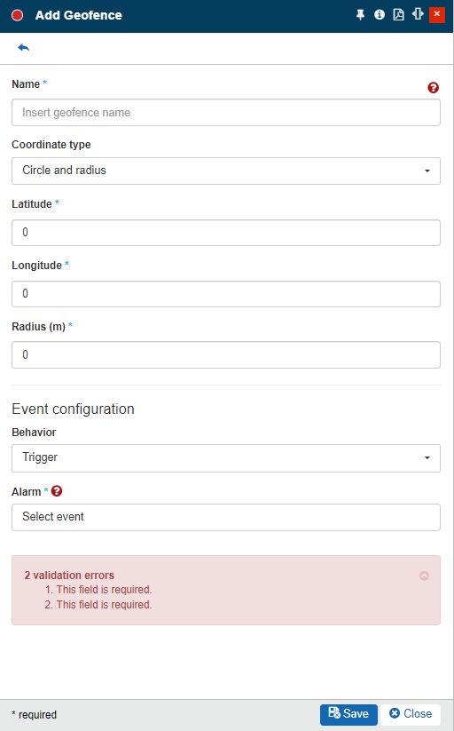
The Add Geofence panel
Name - the unique name of the Geofence. This field is mandatory.
Coordinate type - the coordinate format type, used for the current Geofence geometry definition and handling.
Circle and radius - Circles can be defined manually, by entering a center point using latitude, longitude, and the radius.

Latitude - the latitude coordinate.
Tip
Latitude is a geographic coordinate that specifies the north-south position of a point on the Earth's surface. Latitude is an angle that ranges from -90 degrees to +90 degrees.
Longitude - the longitude coordinate.
Tip
Longitude is a geographic coordinate that specifies the east-west position of a point on the Earth's surface. longitude is an angle that ranges from -180 degrees to +180 degrees.
Radius (m) - the circle radius, measured in meters. This field supports numerical integer values, only.
Tip
The radius of a circle is any of the line segments from its center to its perimeter.
Polygon - Polygons can be defined manually, by entering a list of coordinates. The list of coordinates must end with the first coordinates, to obtain a closed polygon.
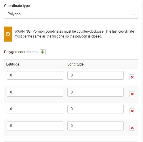
Polygon Coordinates - by default, four polygon coordinates are added to the Add Geofence panel. Polygon Coordinates are also based on Latitude and Longitude parameters.
The user can add more coordinates, by using the Add Polygon Coordinates button
 , or remove redundant coordinates by using the Remove button
  .
.
Behavior - the action occurring in case the Device changes its position, allowing the user to select between the following options:
Trigger - sets the behavior to raise an event.
Suppress - sets the behavior to close an event.
Alarm - the alarm used by the current Geofence, regardless of the selected behavior type. If a device exits or enters a fence, the corresponding action will be performed on the event, as follows:
Event state
Action
Outcome
Closed
Trigger
Open event
Opened
Trigger
Keep event opened
Closed
Suppress
Ignore (keep event closed)
Opened
Suppress
Close event with comment
To preserve the newly created Geofence, the user needs to click the Save button. As soon as the Add Geofence panel is closed, the Geofence is listed under the GPS Tracking panel.
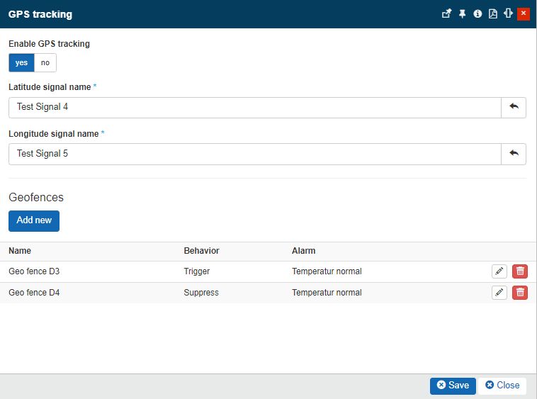
The List of Device's Geofences
Tip
For each device, one or more Geofences can be defined, together with actions that need to be performed.
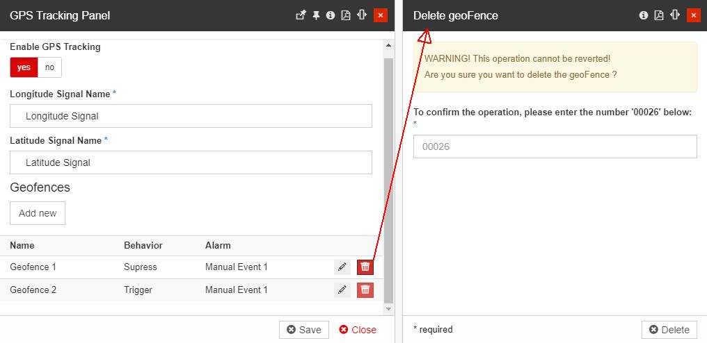
The listed Geofences can be further on managed. as follows:
Edit Geofence - by clicking the
 button, the Edit geofence panel is opened.
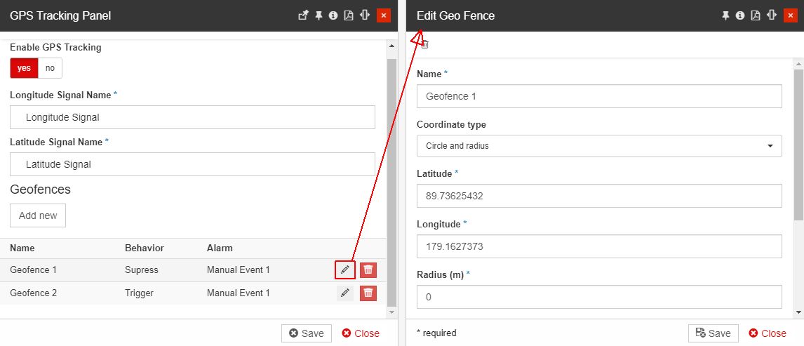
Delete Geofence - by clicking the
 button, the Delete geofence panel is opened.
Important
As soon as the GPS Tracking has been enabled for a Device, the Device details panel is updated, and the Device Map tile is made available.
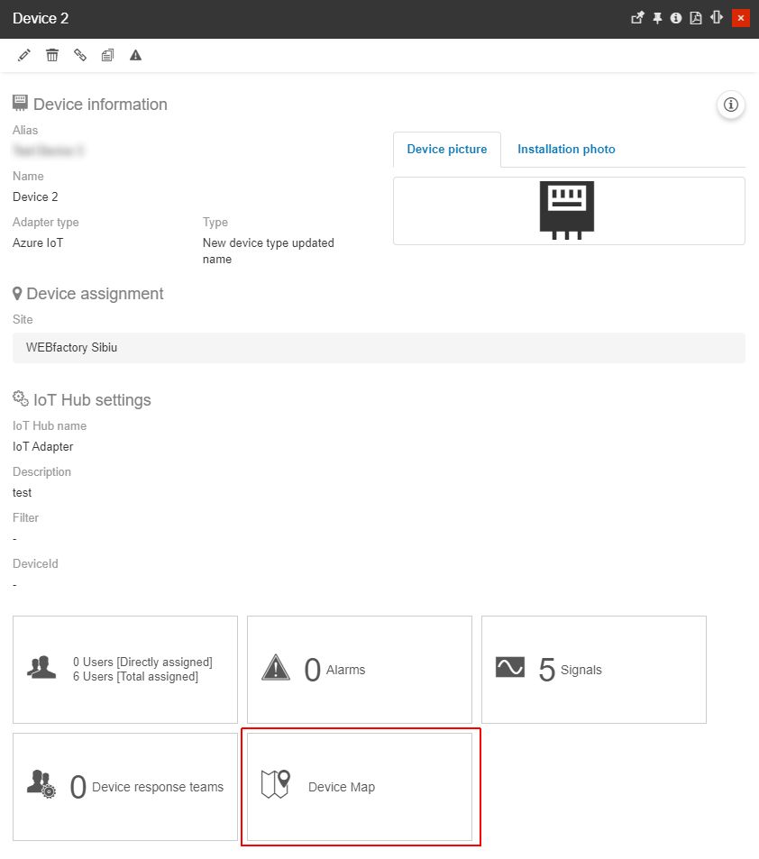
The Device Map tile
Deleting devices
In order to delete a device, the user can click the Delete toolbar button, available in the top toolbar of the Device details panel. By clicking the Delete button the Delete device panel will be opened.
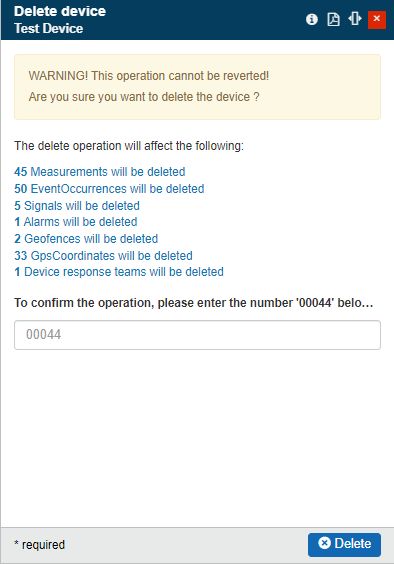
The Delete Device panel
To proceed with device deletion, the user should pay attention to the consequences involved by this operation (the amount of deleted measurements, event occurrences, events, and signals).
A confirmation code is requested in this view. In case the typed deletion code is incorrect, the system will warn the user and prevent the deletion operation.
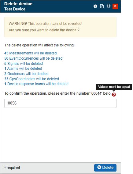
The Deletion code needs to correspond with the provided one
After manually typing the correct deletion code and pressing the Delete button, the device is permanently removed.
The Device Map
The Device Map panel can be accessed by clicking the Device Map tile, of the Device details panel.
Warning
This tile becomes available only for Devices having the GPS Tracking features enabled. For more details on how to enable the GPS Tracking features, please also read the dedicated article, under the Edit devices article.
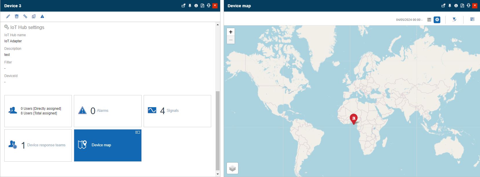
The Device Map panel
In this view, the user can visualize the GPS Tracking and Geofencing information, in a map view. By default, the map is focused on the Device fences and GPS routes.
The toolbar of the Device Map panel features the following options:
the Calendar filter, allowing the user to pick specific time ranges and dates, using the designated pickers, and clicking the Apply button. As soon as the filter is applied, the map view is updated, to only display the GPS routes, contained within the selected time frame.

Note
The Time range and Calendar selectors are used to filter GPS routes, shown on the map.
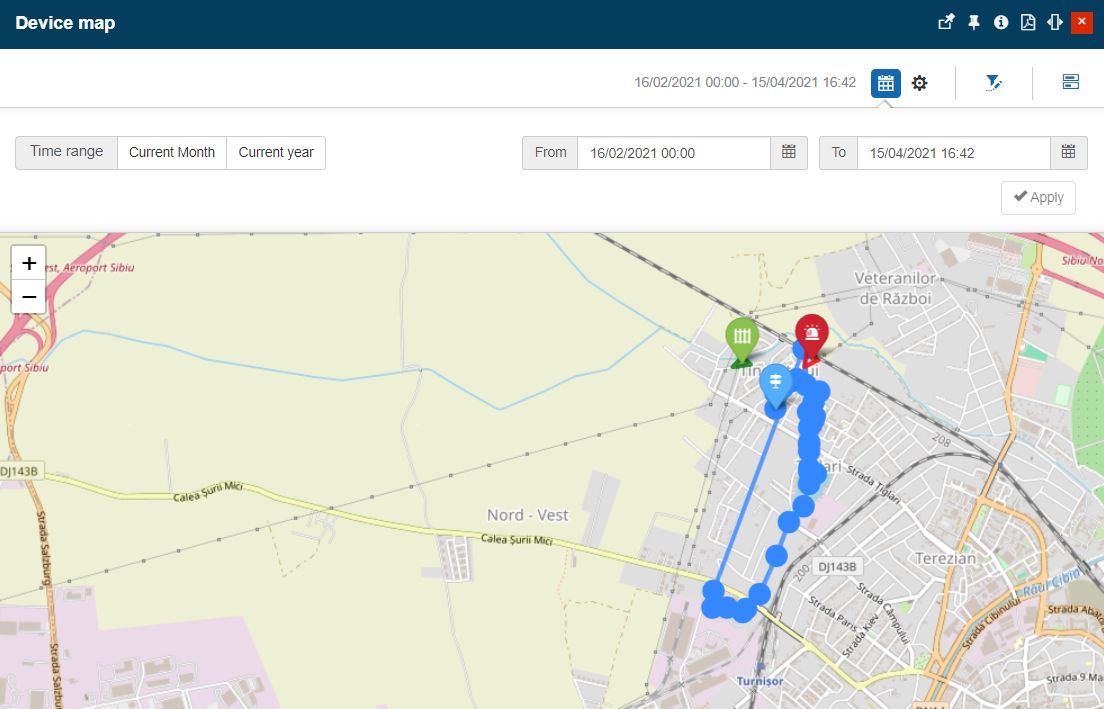
Time-frame filters applied
the Transmission settings selector, allowing the user to decide which layers to be applied on the map view, by choosing from the following options or a combination of those:

GPS routes - displays all the registered Device movements. GPS routes are represented on the map, using the Blue color.
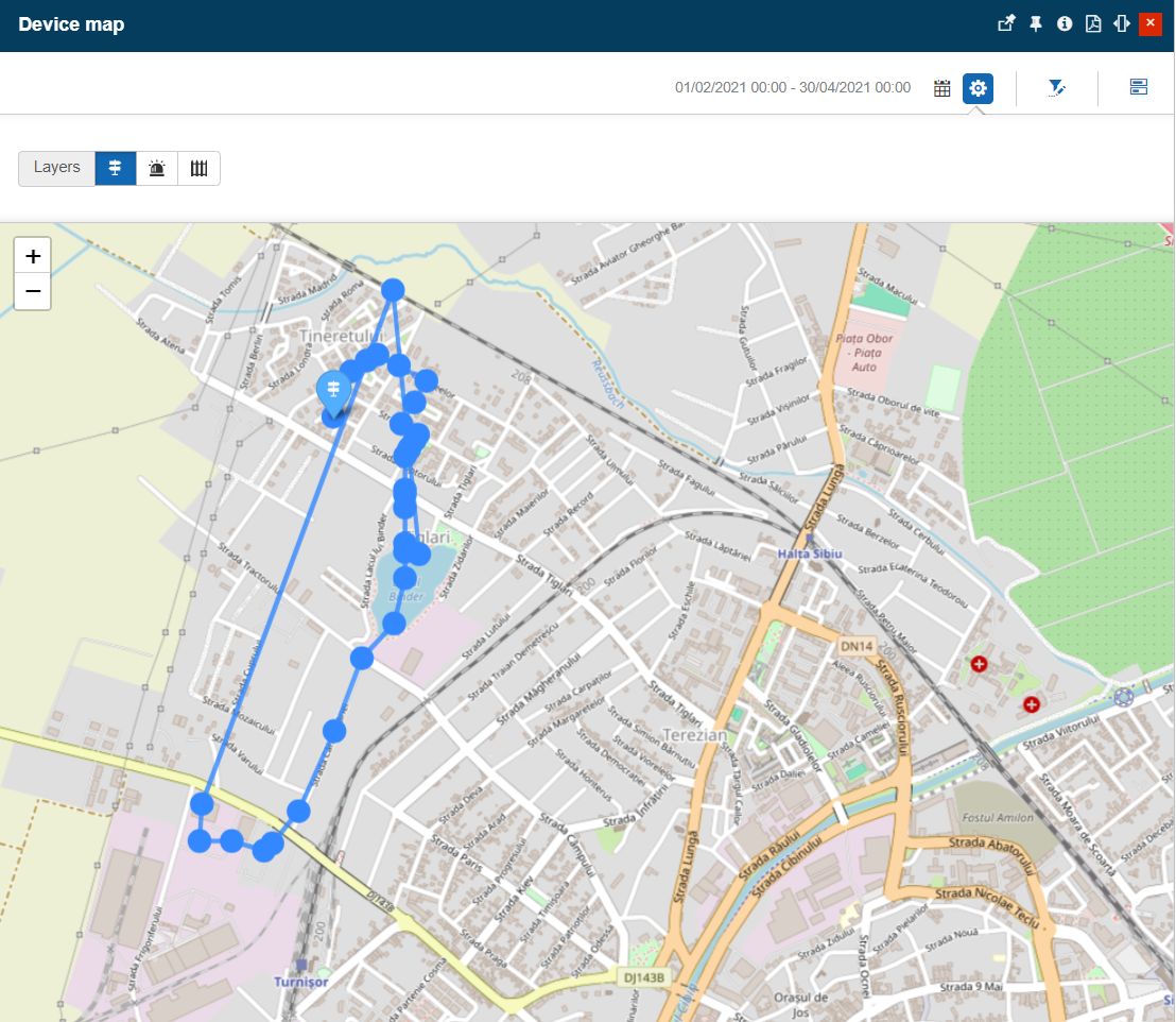
GPS Routes layer enabled
Tip
GPS routes are added automatically on the map view, based on registered Device movements.
Trigger fences - displays all the Device's fences, having the behavior set to "Trigger". The Trigger fences are represented on the map, using the Red color.
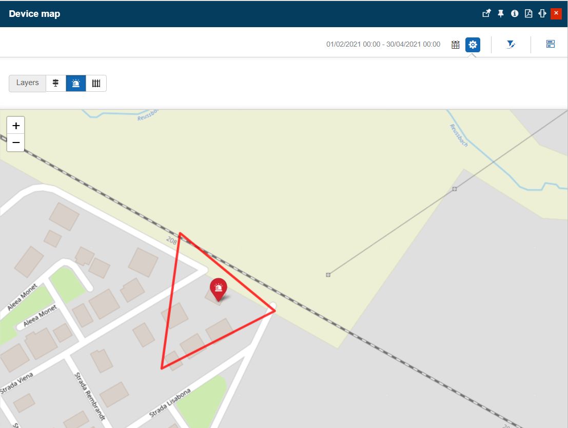
Trigger fences layer enabled
Suppress fences - displays all the Device's fences, having the behavior set to "Suppress". The Suppress fences are represented on the map, using the Green color.
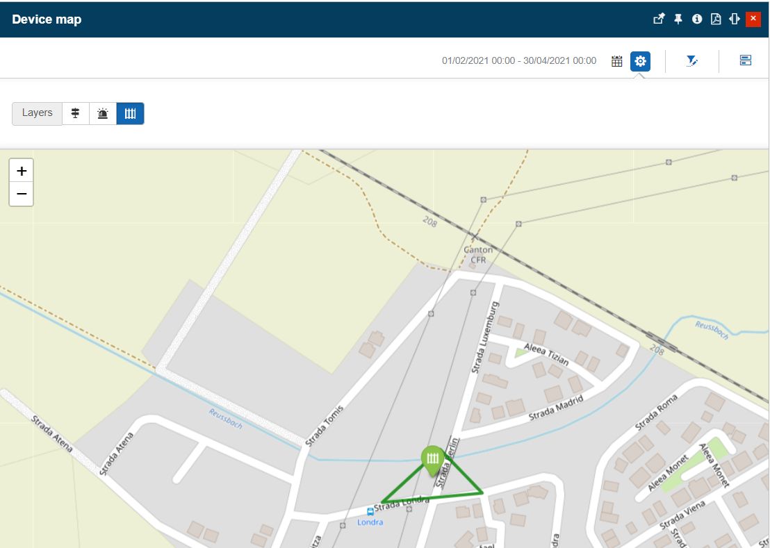
Suppress fences layer enabled
the Open filter selector, allowing the user to apply various entity-based filters, for the fences displayed on the map.
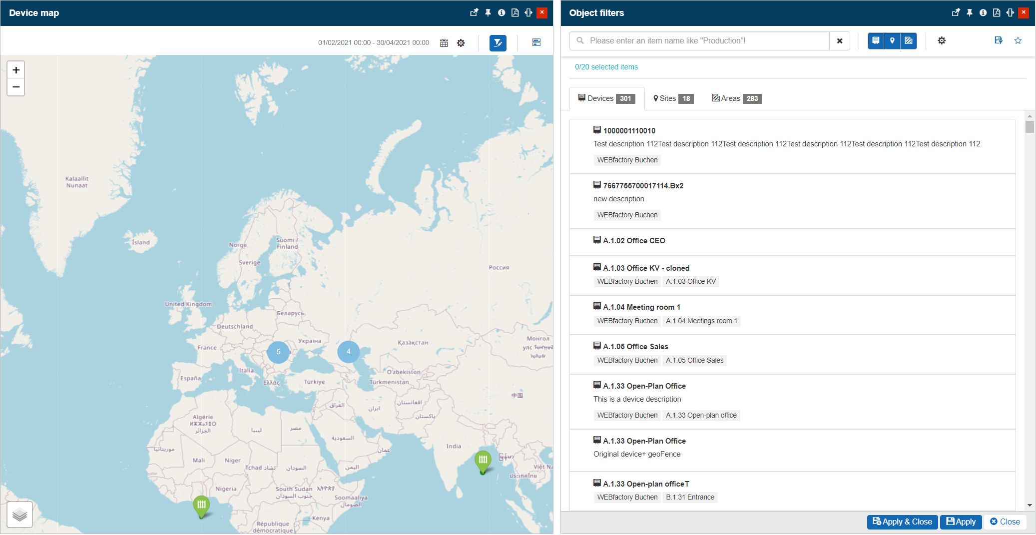
The Object Filters panel
Note
When the Device Map panel is opened in the context of a particular Device, the Object filters will be automatically applied.
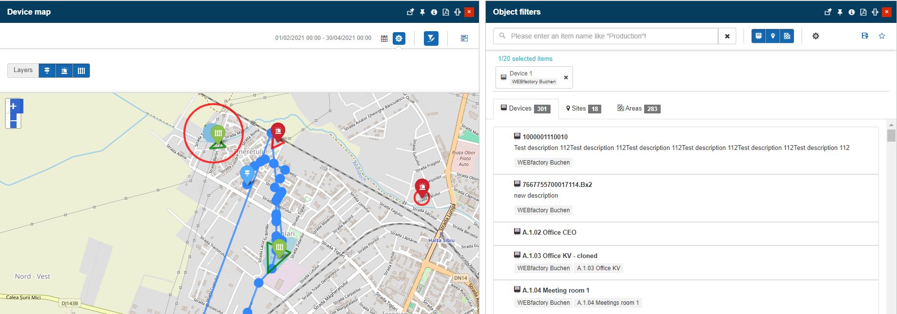
Device filter automatically applied
the Event gantt selector, allowing the user to easily access the Event Gantt panel.
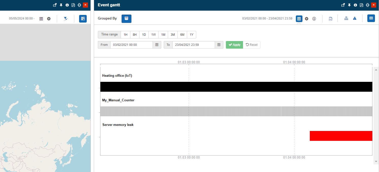
The Event Gantt panel
Tip
For more details about the analysis available in the Event Gantt panel, please also visit the dedicated article, here.
Elements on the map are represented by means of pinpoints. The user can interact with both Geofences and GPS Routes pinpoints, in order to view more details about the involved Device and the triggered alarms.
Therefore, by clicking on a Geofence pinpoint, on the map view, a dialog is displayed, allowing the user to open the following drill-down panels:
Open the Device details panel.
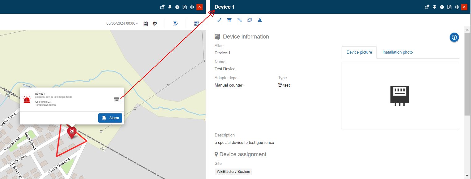
Open the Event gantt panel, focused on the involved Device.

By clicking on a GPS Route pinpoint, on the map view, a dialog is displayed, allowing the user to open the following drill-down panel:
Open the Device details panel.
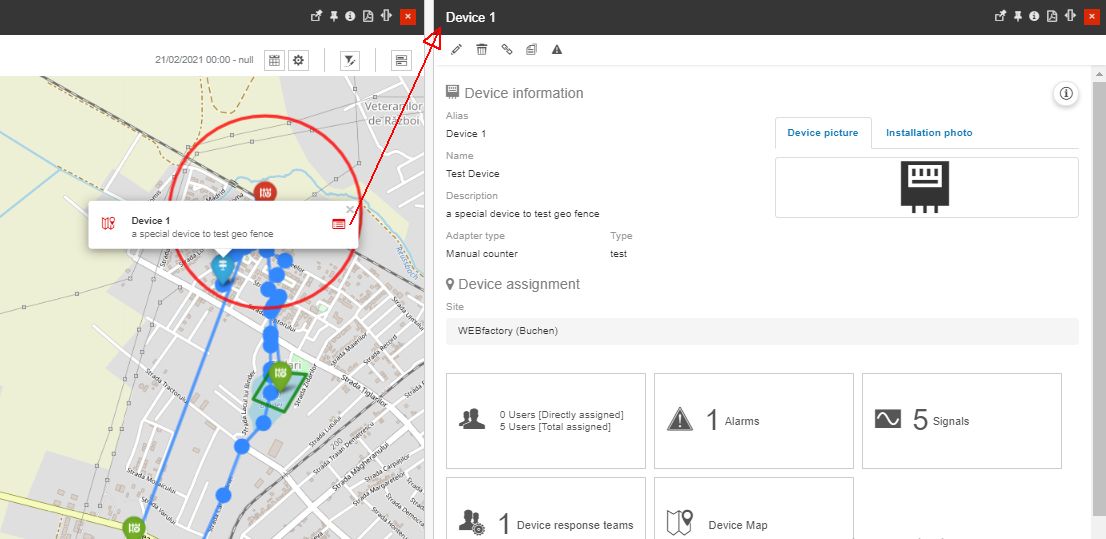
Managing Application Mappings
The Manage Application button displayed in the Device's details panel allows users, having the Manage device applications permission enabled, to add and update a Device's i4designer Application mapping.
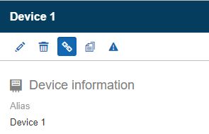
The Manage application button
Tip
For more details about the i4designer Application mapping feature please also refer to the dedicated articles here.
The Manage Application Mappings panel of a Device features the following properties:
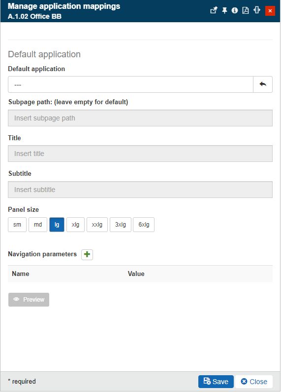
The Manage Application Mappings panel
Default Application - the application added in this section will be displayed in the Device's details panel.
Default Application - the Application mapping used by the current Device, that will be displayed in the Devices' details panel.
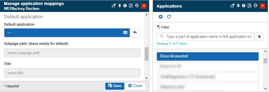
The list of Application mappings
Warning
Please note that the Application mappings list will be available when accessed from the Manage Application Mappings only for users having at least the View applications permission enabled. The list will display only Applications owned by or assigned to the logged-in user.
Subpage path - an optional sub-page of the i4designer project. The sub-page path is given by the project's sub-page exact name.
Note
By setting a sub-page path the page will be by default displayed by the device application. If the field is left empty, the project's default page will be displayed.
Title - the title displayed by the panel, when opening the Application in view or preview mode. If no title is filled in this field, the Application panel will display the name of the application mapping.
Subtitle - the sub-title displayed by the panel, when opening the Application in view or preview mode. If no sub-title is filled in the field, the Application panel will display no sub-title.
Panel size - the size of the panel, when opening the Application in view or preview mode. By default, the panel size is set to lg (large) but the user can decide to apply the following sizes: sm (small), md (medium), lg (large), xlg (extra large), xxlg (extra extra large), 3xlg (3 times extra large), 6xlg (6 times extra-large).

The Panel size selector
Navigation parameters - an optional set of parameters based on key-value mappings.
Navigation parameters can be added by clicking the Add parameter button
 . The user needs to manually input the Parameter Name and Value. Inserted parameters can be removed by clicking the Delete button
  .
.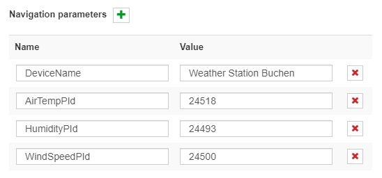
The Navigation parameters
Tip
For a step-based tutorial describing the usage of Navigation parameters, please follow the dedicated article, here.
Besides the custom navigation parameters, the i4connected platform is also injecting a set of standard parameters. The standard parameters are capable to automatically resolve parsed information.
This table lists the parameters that can be used by the application designer and which will be automatically available to the applications targeting the i4connected platform:
I4C_SITE_ID - Contains the ID of the site to which the application is attached. Injected via query parameters.
Note
Available if the application is attached to:
A site
An area
A device connected to a site
I4C_SITE_NAME - Resolved at startup, it contains the name of the site (untranslated).
Note
Available if the application is attached to:
A site
An area
A device connected to a site
I4C_AREA_ID - Contains the ID of the area to which the application is attached. Injected via query parameters.
Note
Available if the application is attached to:
An area
A device connected to an area
I4C_AREA_NAME - Resolved at startup, it contains the name of the area (untranslated).
Note
Available if the application is attached to:
An area
A device connected to an area
I4C_ORG_ID - Contains the ID of the organizational unit to which the application is attached. Injected via query parameters.
Note
Available if the application is attached to:
An organizational unit
A device connected to an organizational unit
I4C_ORG_NAME - Resolved at startup, it contains the name of the organizational unit (untranslated).
Note
Available if the application is attached to:
An organizational unit
A device connected to an organizational unit
I4C_DEVICE_ID - Contains the ID of the device to which the application is attached. Injected via query parameters.
Note
Available if the application is attached to:
A device
I4C_DEVICE_NAME - Resolved at startup, it contains the name of the device.
Note
Available if the application is attached to:
A device
I4C_DEVICE_DESCRIPTION - Resolved at startup, it contains the description of the device.
Note
Available if the application is attached to:
A device
I4C_DEVICE_ALIAS - Resolved at startup, it contains the alias of the device.
Note
Available if the application is attached to:
A device
Note
Empty Application mappings will not be visible in the detailed view mode of a Device.
While configuring the Default Application, the user can check the Application's display in preview mode. By clicking the bottom Preview button a separate panel is opened displaying the drill-down Application as it will be displayed in view mode.
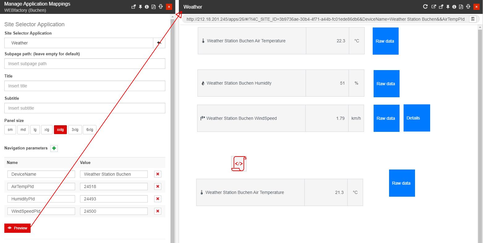
Example of Application opened in preview mode
While in preview mode, the user can assess the Application before saving and applying the settings.
Further on, the URL of the Application is displayed at the top of the preview panel allowing the user to copy it to the clipboard. The copied URL can be afterward used to pin tiles to i4connected pages.

The Copy URL to clipboard option
Tip
For more details about the Pin tiles option, please also visit the dedicated article.
Cloning devices
Often, the devices of a hierarchical entity have similar or identical structures, settings, and signals. To reduce the implied amount of work, the clone functionality offers a quick way to add multiple device structures with minimal configuration.
The Clone device panel can be accessed by clicking the Clone device toolbar button of the Device detailed view panel, by all users having the Manage devices permission enabled.
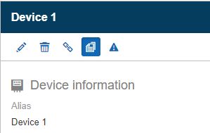
The Clone device button
In this view the user can proceed with the following settings:
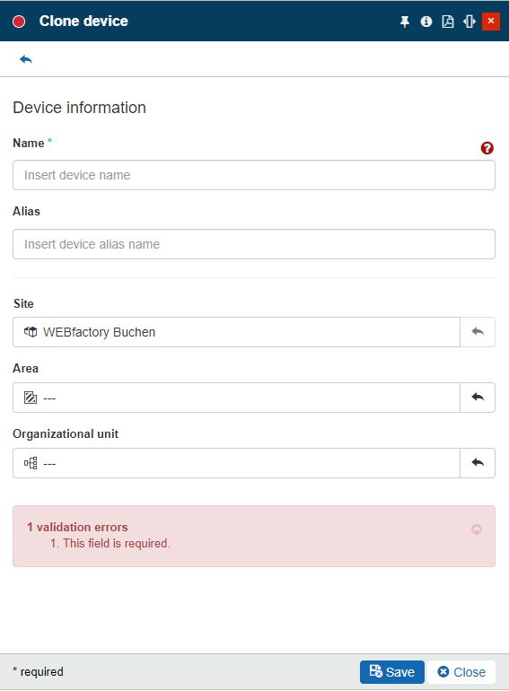
The Clone device panel
Name - the name of the device clone.
Important
The name is a unique device property, hence the user is required to manually fill in the name of the device clone.
A validation error will be displayed in an attempt to clone a device with an already existing name.

Alias - The friendly name of the device clone. The device alias will be displayed in the device card when listed.
Note
This field is not mandatory, but please note that the alias of the parent device will be reused if a new one is not added.
As the list of devices shows by default the alias and not the name, you may have multiple devices with the same alias in the list.
Site - the site where the device should be assigned after cloning. By default, this field is populated with the source device information, but the user can decide to change the hierarchical entity assignment.
Area - the area where the device should be assigned after cloning. By default, this field is populated with the source device information, but the user can decide to change the hierarchical entity assignment.
Organizational unit - the organizational unit where the device should be assigned after cloning. By default, this field is populated with the source device information, but the user can decide to change the hierarchical entity assignment.
If clicking the Close button the Clone device panel is closed without creating a new device.
By clicking the Save button the clone device operation will run in the background as it may take a longer time to complete. When finalizing the cloning process system displays a notification in the Background operation area of the Ewon by HMS Networks global menu bar.
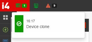
The Device clone notification
Consequently, an event is automatically triggered by the system. The event will be closed within a matter of seconds, therefore it will be visible in the Historical Alarms list.
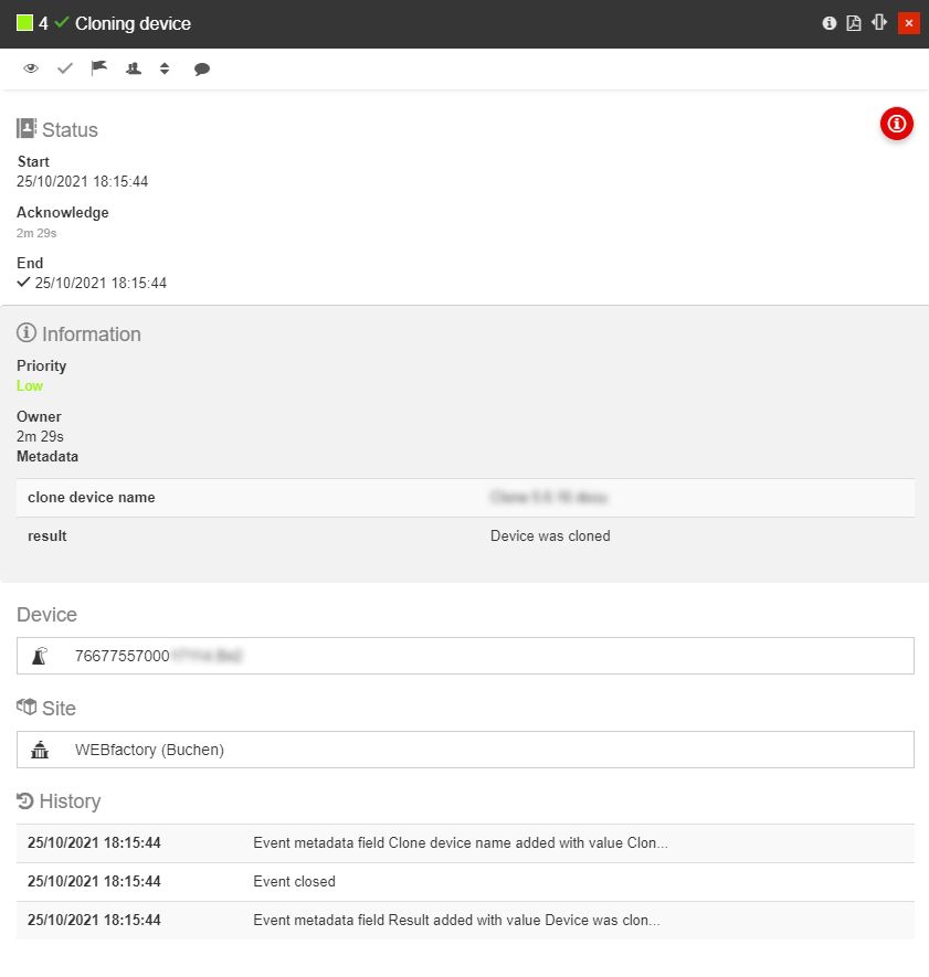
The "Cloning device" event occurrence
When the cloning operation is complete, the clone becomes a separate device, even though it shares the following properties with the parent device:
Device description
Device photo
Device installation photo
Device flags (Visible and Active)
Device type
Device manufacturer
Device model
Device hardware version
Device software version
Device site (if it was not changed in the Clone device panel)
Device area (if it was not changed in the Clone device panel)
Device organizational unit (if it was not changed in the Clone device panel)
Device adapter
Device signals
Device users
Device alarms
Device external alarms
Device suppression settings
Device Overwrite event priority settings
Device advanced settings, such as Deadband, Plausibility Delta, Gap interval, Interpolation, Inactivity interval, and Stale data detection interval.
These settings can be changed at any point in time in the Edit device panel.
Publishing Manual Events
Users having the Publish manual event from devices permission enabled can manually trigger an alarm in the context of the currently selected Device, by clicking the Publish manual event toolbar button.
Warning
The Publish Manual Event button will be hidden for Devices having the Alarm suppression feature enabled.
As soon as the Publish manual event button is clicked the Select Manual Event panel is opened.
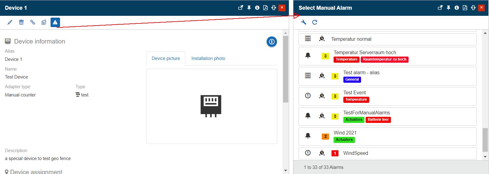
Publish Manual Events from Device context
The Select Manual Event panel lists all the Manual events available for triggering an alarm. The list display is conditioned by the user's permissions, hence only users having the View Events permission enabled will be allowed to proceed with this action.
After selecting the desired Manual Event, the Publish Manual Alarm panel is opened. In this view, the user is required to type in a comment that will accompany the event occurrence. Further on, the Alarm priority selector allows the user to apply the system default priority (which is either the event original priority, or the priority selected for the Device as Overwrite event priority), or choose a different priority from the Priorities list.
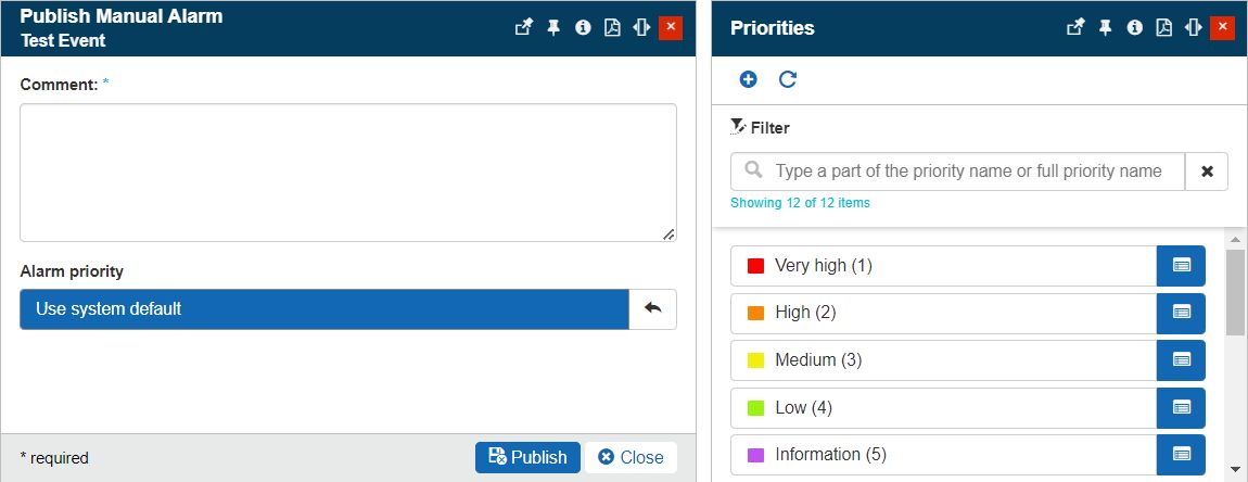
The Publish Manual Alarm panel
Tip
For more details about the management of Manual events please visit the dedicated article here.