Signal Details Panel
Signals are the basic components of your WEBfactory 2010 Studio Project. Learn everything you need to know about the WEBfactory 2010 Signals.
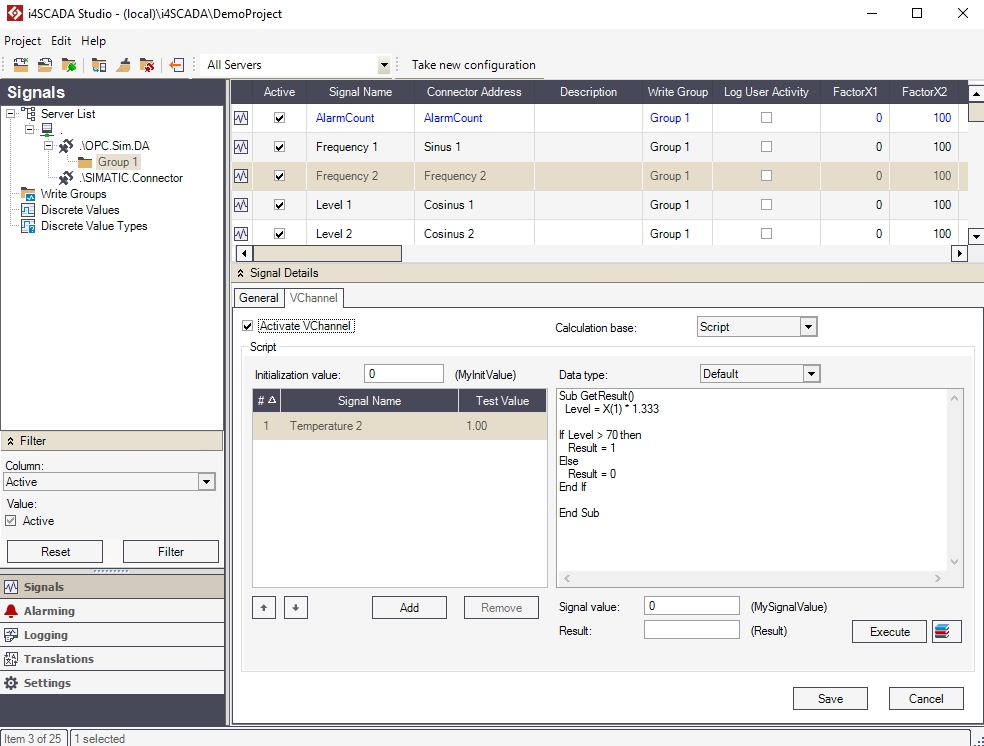
The Signal Details panel, located at the bottom of the main view, displays the complete set of signal properties. The same properties are available in the signals grid. The Signals Details panel is split in two tabs: General, containing the general signal properties and VChannel, containing the virtual channels and scripts-related signal properties.
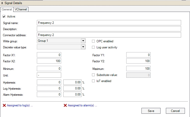
The General and VChannel tabs of the Signal Details panel
Warning
Any change applied in the Signal Details panel is applied only when the Save button is pressed.
The General tab contains the general signal properties. These properties can be found also in the signals grid.
UI Option | Description |
|---|---|
Active | If checked, the signal is active in WEBfactory Server. |
Signal name | The name of the signal in WEBfactory Studio. |
Description | Optional signal description. |
Connector address | The address of the signal in the OPC server. |
Write group | The write group to which the signal belongs. |
Discrete Value Type | The combining group of discrete values. The discrete values are used by Ewon by HMS Networks Scheduler to manipulate a device depending on the hour of the day. The Discrete Value Type containing several discrete values can be attached to a process signal (in the Signal list) so that Ewon by HMS Networks Scheduler can assign the value of one of the Discrete Values inside the Discrete Value Type to the process signal when needed. |
OPC enabled | Works in conjunction with the Ewon by HMS Networks Server acting as an OPC server (usually the Ewon by HMS Networks Server acts as an OPC client). When this option is enabled, the signal value will be sent to the Ewon by HMS Networks WCS OPC server, so other OPC clients can access the value from the Ewon by HMS Networks Server like from an OPC server. |
Log User Activity | If checked, the user activity for this signal will be logged. |
Factor X1 | A real value of the PLC used to transform the signal value using a mathematical formula into a SCADA readable value Y1. The transformation is based on a XOY coordinate system and needs 4 values (X1, X2, Y1, Y1) to be applied. 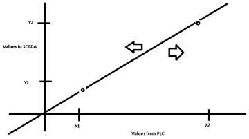 |
Factor X2 | A real value of the PLC used to transform the signal value using a mathematical formula into a SCADA readable value Y2. The transformation is based on a XOY coordinate system and needs 4 values (X1, X2, Y1, Y1) to be applied. |
Factor Y1 | The SCADA value of the X1 PLC value. The transformation is based on a XOY coordinate system and needs 4 values (X1, X2, Y1, Y1) to be applied. |
Factor Y2 | The SCADA value of the X2 PLC value. The transformation is based on a XOY coordinate system and needs 4 values (X1, X2, Y1, Y1) to be applied. |
Minimum | Sets the minimum signal value for writing. If a value smaller than this limit is written, the minimum value will be sent to the control unit. |
Maximum | Sets the maximum signal value for writing. If a value bigger than this limit is written, the maximum value will be sent to the control unit. |
Unit | Optional measurement unit for the signal's value. If present, the unit can be used further in visualizations. |
Substitute value | Enables the usage of the substitute values. If checked, a substitute value is used when the minimum value is not reached or the maximum value is exceeded. |
Hysteresis | Sets absolute or relative hysteresis value for signal visualization. Here, hysteresis refers to the difference between consecutive signal values of a signal. Only field-level signal values are taken into account. |
Log Hysteresis | Sets absolute or relative hysteresis value for logs. Here, hysteresis refers to the difference between consecutive signal values of a signal. Only field-level signal values are taken into account. |
Alarm Hysteresis | Sets absolute or relative hysteresis value for alarms. Here, hysteresis refers to the difference between consecutive signal values of a signal. Only field-level signal values are taken into account. |
Assigned to log(s)... | Notifies the user if the selected signal is assigned to any logs. Clicking on the link will open the logging panel. |
Assigned to alarm(s)... | Notifies the user if the selected signal is assigned to any alarms. Clicking on the link will open the alarming panel. |
The VChannel tab allows the user to generate virtual signals in Ewon by HMS NetworksStudio. The virtual signals can be used to create scripts for various tasks using different signal values or to generate collective alarms.
Learn more about WEBfactory 2010 Virtual Channels and Scripting from the article here.
The virtual signals are created using VChannels (virtual channel). The VChannel's input parameters are the signal values. Several VChannels can be linked one to another.
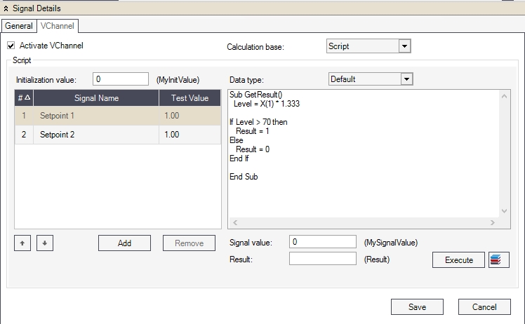
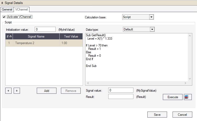
The VChannel tab
The VChannel can be activated or deactivated using the Activate VChannel checkbox. The Calculation base of the VChannel can be either Script or Collective Alarm.
The Script calculation base allows the user to define a VB script in the script editor using signal variables as input signals.
UI Option | Description |
|---|---|
Initialization value | Sets a constant (named MyInitValue). When the system starts, the MyInitValue constant will be made available. |
Data type | Set the data type for the WriteSignal () function. Can be:
|
 | Input signal's index number. Input signals are referenced in the script by index numbers. |
 | Move the input signal up in the list. The signal's index number changes. |
 | Move the input signal down in the list. The signal's index number changes. |
Add | Opens the Select Parameter window that allows the user to add signal as input signals. |
Remove | Remove the selected input signal. |
Signal value | Sets the starting signal value for the MySignalValue variable. The MySignalValue variable is used to query the value of the virtual signal variable. |
Result | The resulted value is calculated by testing the script and corresponds with the value of the VChannel at run time. |
Execute | Runs the script. |
 | Open the VChannel Library functions window and allows the user to add functions from the library to the script editor. |
The script editor contextual menu gives the user quick access to Input Signals and Library Functions.
The Collective Alarms calculation base allow the user to integrate several alarms in a VChannel as a collective alarm. The value of the virtual signal at run time will be the number of active alarms from the Collective Alarms.
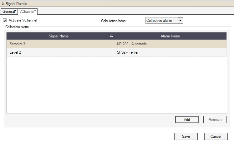
Collective alarms
UI Option | Description |
|---|---|
Signal Name | The name of the signal attached to the alarm. |
Alarm Name | The name of the alarm. |
Add | Opens the Collective Alarms window and allows the user to add alarms to the VChannel. |
Remove | Removes the selected alarms. |
Select Parameters Window
Check out this article and learn how to select parameters for the WEBfactory 2010 Studio Signals.
The Select Parameters window allows the user to add signal variables as input parameters in the VChannel scripts. The signals grid lists the available signals, displaying the Signal Name, Connector address and the OPC Enabled parameters of every available signal.
The user can select multiple signals to be added as input variables to the script calculation base of the VChannel by holding the Ctrl key and selecting the signals or toggle selections by using the Select All and Invert Selection buttons.
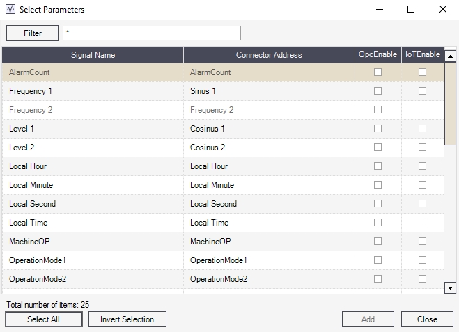
The Select parameters window
The Select Parameters dialog supports filtering and the usage of wildcards.
Collective Alarms Window
Check out this article and learn more details about the Collective Alarms window in the WEBfactory 2010 Studio application.
The Collective Alarms window allows the user to select alarms and add them to the VChannel as collective alarms. The alarms are listed along with their Alarm Name and the name of the associated signal in the alarm grid.
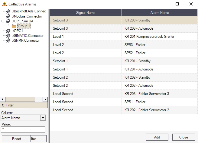
Adding collective alarms
The tree view allows the user to select different connectors and different alarms for adding them as collective alarms.
Tip
Multiple items can be selected by clicking on them while holding down the Ctrl key.
The user has the possibility to filter the alarms based on the columns form the main view and their values.
Virtual Channels and Scripting
This article describes the WEBfactory 2010 Studio Virtual Channel Signals and how to use the scripting function.
WEBfactory 2010 allows the creation of virtual signals (VChannels) which are not loaded using any connector. Virtual signals can be used for different purposes – e.g. sum calculation of various entry signals, collective alarms generation
Scripts make possible the merging of different process variables, via simple calculation specifications, as well as complex processing of script functions.
Scripts are always carried out on WEBfactory 2010 server-side.
Library functions make the use of recurring script blocs easy and maintainable.
Using the ReadSignal and WriteSignal functions, scripts may access process variables.
VChannels are created and compiled in the WEBfactory 2010Studio. The procedure of adding VChannels is analogue to the adding of regular signals.
VChannels are color-coded differently (blue), unlike regular signals.
In order to handle a signal as VChannel, the Activate VChannel check box must be set.
The image below explains the configuration of VChannels:
Entry parameters (entry signals). Each time an parameter value changes, the script of the VChannel will be triggered.
VChannel calculation script (VBScript).
The script can be test run directly after the configuration.
The VChannels calculation basis can be one of the following:
Script
Collective alarm
When using a script as a base of calculation, generally all possibilities of the WindowsScriptingHost can be used. Using VBScript script language both simple functions (e.g. reading and writing process variables and database access) as well as complex operations at the operative system level (e.g. WMI, FSO) are possible.
Note
The maximum size of the script is 5000 characters.
A collective alarm allows various alarms to be summarized. The virtual signal value will show at run time the amount of selected activated alarms.
Examples
Summing of two process values and subsequent output
Script:
Sub GetResult()
	Result = X("Setpoint 1") + X("Setpoint 2")
End Sub
The process signals Setpoint 1 and Setpoint 2 are defined as entry signals for this VChannel:
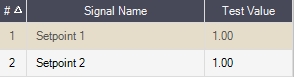
Entry parameters can be accessed by different syntaxes in the script: X(„SIGNAL NAME“) or X(INDEX NUMBER OF ENTRY ITEM) – e.g. X(1).
Writing to other process signals depending on the entry signal
Script:
Sub GetResult()
If (X(1) > 0) Then
            WriteSignal "Setpoint 1", 1,"",""
            WriteSignal "Setpoint 2", 1,"",""
            WriteSignal "Setpoint 3", 1,"",""
            Result = 1
        Else
            WriteSignal "Setpoint 1", 0,"",""
            WriteSignal "Setpoint 2", 0,"",""
            WriteSignal "Setpoint 3", 0,"",""
            Result = 0
        End If
End Sub
ReadSignal and AckAlarm are other WEBfactory 2010 standard functions.
Database query and result output in the VChannel script
In the following example, the number of rows in the Signals table is returned.
Script:
Sub GetResult()
    Set cn = CreateObject("ADODB.Connection")
    Set rs = CreateObject("ADODB.Recordset")
    cn.Open("Provider=SQLOLEDB.1;Persist Security Info=False; Data Source=(local)\WEBfactory2010;Initial Catalog=DemoProject;User Id=sa;Password=webfactory")
    rs.Open "SELECT COUNT(*) FROM Signals", cn
    Result = rs.Fields(0).value
    cn.Close()
End Sub
Use of script libraries
Especially in the case of recurring functions (e.g. conversions) it is advisable to store them in a VChannel library.
In the following example the temperature value is converted from Celsius to Fahrenheit:
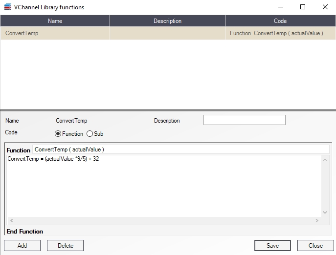
The call-up of this function in the VChannel:
Sub GetResult()
    Result = ConvertTemp(X(1))
End Sub
VChannel Library Functions Window
Before using the VChannel Library function please read this article and learn more about it.
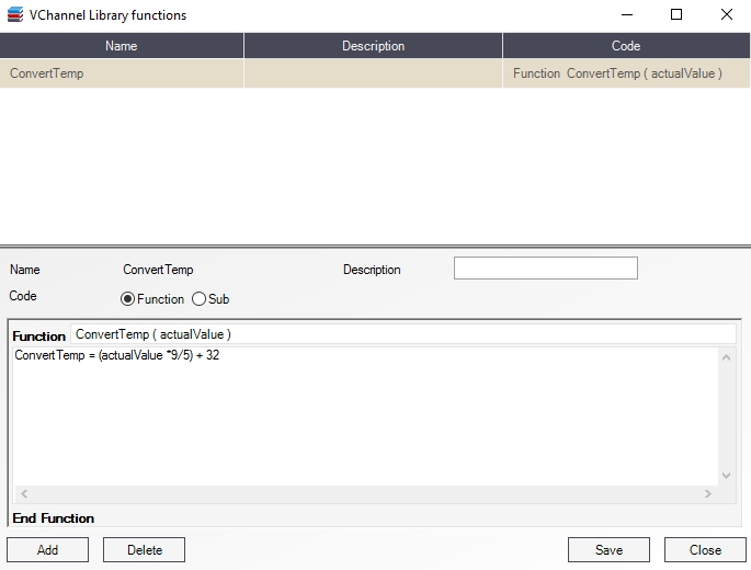
The VChannel Library Functions window allows the user to add functions from the library to the script editor. The functions are listed in the grid along with their Name, Description and Code properties.
Scripts Library
Functions can be defined and stored in the library using the Function Builder.
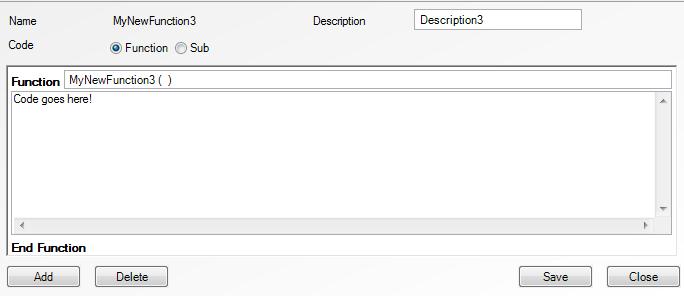
The Function builder
UI Option | Description |
|---|---|
Name | Displays the name of the function. |
Description | The function's description. |
Code | The code editor can define functions or subs. Functions: 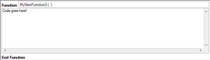 Subs: 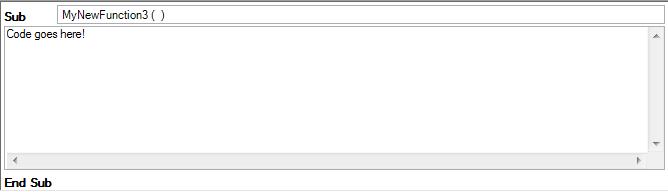 |
Add | Adds the function to the library. |
Delete | Deletes the selected function from the library. |
Save | Saves the changes. |
Close | Closes the function library. |