Using the Binary Masks in Controls with States Editor (SmartEditor and Expression Blend)
Some of the Ewon by HMS Networks controls have a different approach on setting up the visual states at design time. Ewon by HMS Networks controls like WFStatesButton1 and WFStatesToggleButton1 use the States Editor for managing the visual states settings.
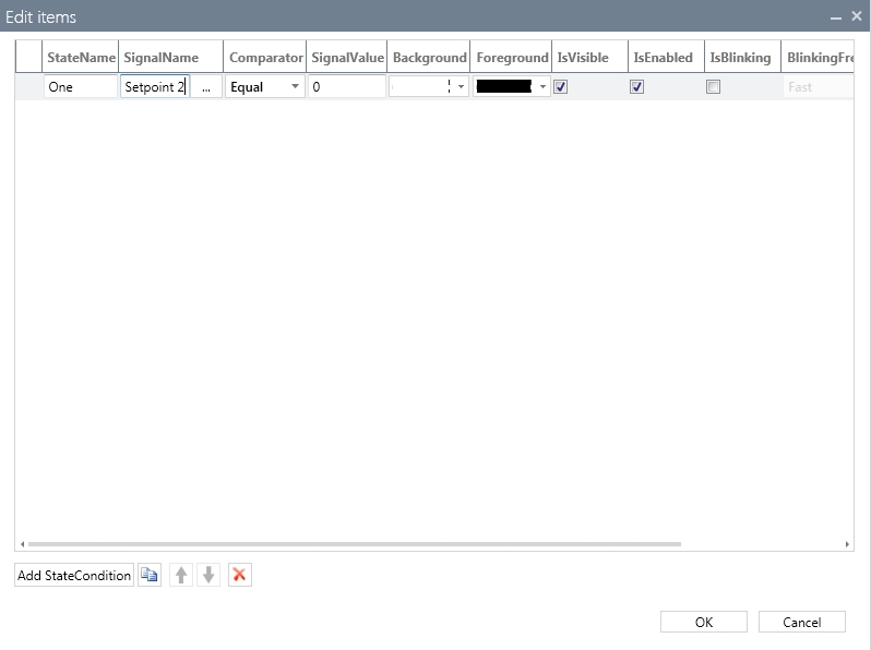
The States Collection Editor of WFStatesButton1
One important property of the States Collection Editors method of handling the design time setup of visual states is the ability to use comparators between a signal value and a constant (named SignalValue) by simply selecting the desired comparator from the drop-down menu.
In order to use binary values and apply a binary masks (a logical AND operation between the binary value of the signal and the SignalValue constant) for the different visual states, the user must use the AndWord or AndDWord comparators.
Just like the WFIndicator1 example, the control will enter in a certain visual state when the result of the logical AND operation between the value of the signal and the SignalValue constant equals the SignalValue constant of that specific state.
Example use case
The PLC sends a signal as a WORD with 16 Bits. Each bit represents a separate binary information. For example:
Bit 0 is 1 - Pump A is running
Bit 1 is 1 - Pump B is running
Bit 2 is 1 - Pump C is running
etc.
The user is able to use this single WORD signal to display information about all the Pumps.
Using the information above, the user must set up the WFStatesButton1 control to turn yellow when Pump A is running, green when Pumps A and B are running and blinking green when all three Pumps are running.
Any Ewon by HMS Networks control that supports dynamic visual states through the States Editor can be used!
The implementation of this use care will be treated below in both SmartEditor and Blend.
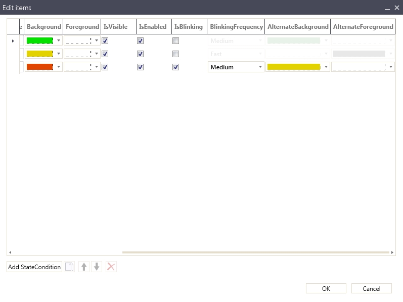
SmartEditor implementation
While we are using a single signal to drive the WFStatesButton1 control, we will need to set up the SignalValue constants in such a manner that the states will be activated correctly.
Select the WFStatesButton1 and click on the States button from the Signals property tab.
The States Collection Editor button
In the States Collection Editor window, create three different state conditions by clicking the Add StateCondition button. Each state condition will represent the current running Pumps:
The first state, when all three Pumps are running (named ABC).
The second state, when only Pumps A and B are running (named AB).
The third state, when only Pump A is running (named A).
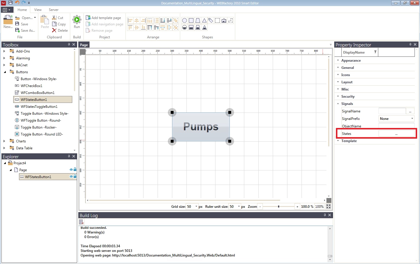
As our state information is driven by a single signal, use the same SignalName for all of the three StateConditions. In our use case, the signal used is Setpoint 2. Select AndWord as comparator between the SignalName signal and the SignalValue constant.
AndWord is used when working with 16 bits values (up to 32.767). For 32 bits values, the AndDWord comparator should be used.

Using the same signal in all StateConditions
Next, we need to assign the proper constants for the SignalValue parameter of each state. In out use case, each one of the first three bits of the signal value represent a Pump. This means that the SignalValue constant for the first state must have the first three bits as 1, meaning that all three Pumps are running. Thus the SignalValue constant of the first state will be 7 (111 in binary). Following the same logic, the SignalValue constant of the second state will be 3 (011 in binary), and the SignalValue constant of the third state will be 1 (001 in binary).
Setting up the StateConditions for WFStatesButton1
IMPORTANT: The order of the StateConditions is crucial!
In the States Collection Editor, the first state has the highest priority. In our case, all SignalValue constants have the first bit equal to 1. If the order of the states would have been reversed, the condition for the first state would have been met throughout all the defined states, and because the priority rule, only the first state would have been applied.
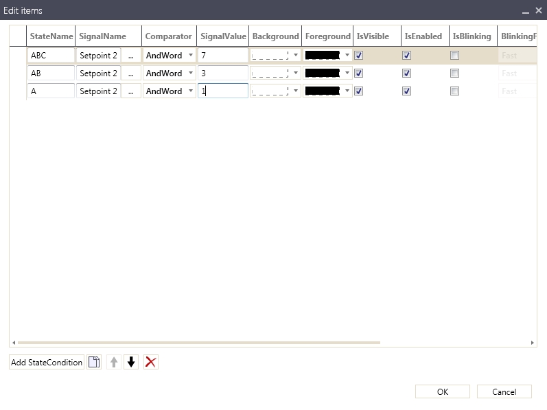
Set up each of the states visual attributes accordingly to the project's requirements. In our use case, we will be using the following model:
For the first state, when all the three Pumps are working, the Background color will be green and the Foreground white.
For the second state, when only Pumps A and B are working, the Background color will be yellow and the Foreground white.
For the last state, when only Pump A is running, the Background color will be red and the Foreground white. Also, the IsBlinking option will be marked for this state, with the BlinkingFrequency on Medium, the AlternateBackground yellow and the AlternateForeground white. This means that the control will blink red and yellow when only one pump is running.
Run the visualization and use the Ewon by HMS NetworksTest Center to test the control. Use the Setpoint 2 signal and enter the values 7, then 3 and the 1 and notice the changes. The control will display each state depending on the value of the Setpoint 2 signal.


The three states of the WFStatesButton1 control.
When using binary values, not only the exact decimal value used as signal value constant will trigger the associated state. Any other value that, in binary mode, has the same bits equal with 1 will trigger the state.
For example, the second state is triggered when the Setpoint 2 value is 3 (011 in binary mode). The same state will be triggered when the Setpoint 2 value is 11 (1011 in binary mode).
Blend implementation
Select the WFStatesButton1 and expand the WEBfactory 2010 - States property category from the Properties panel. Click the button next to the States (Collection) option.
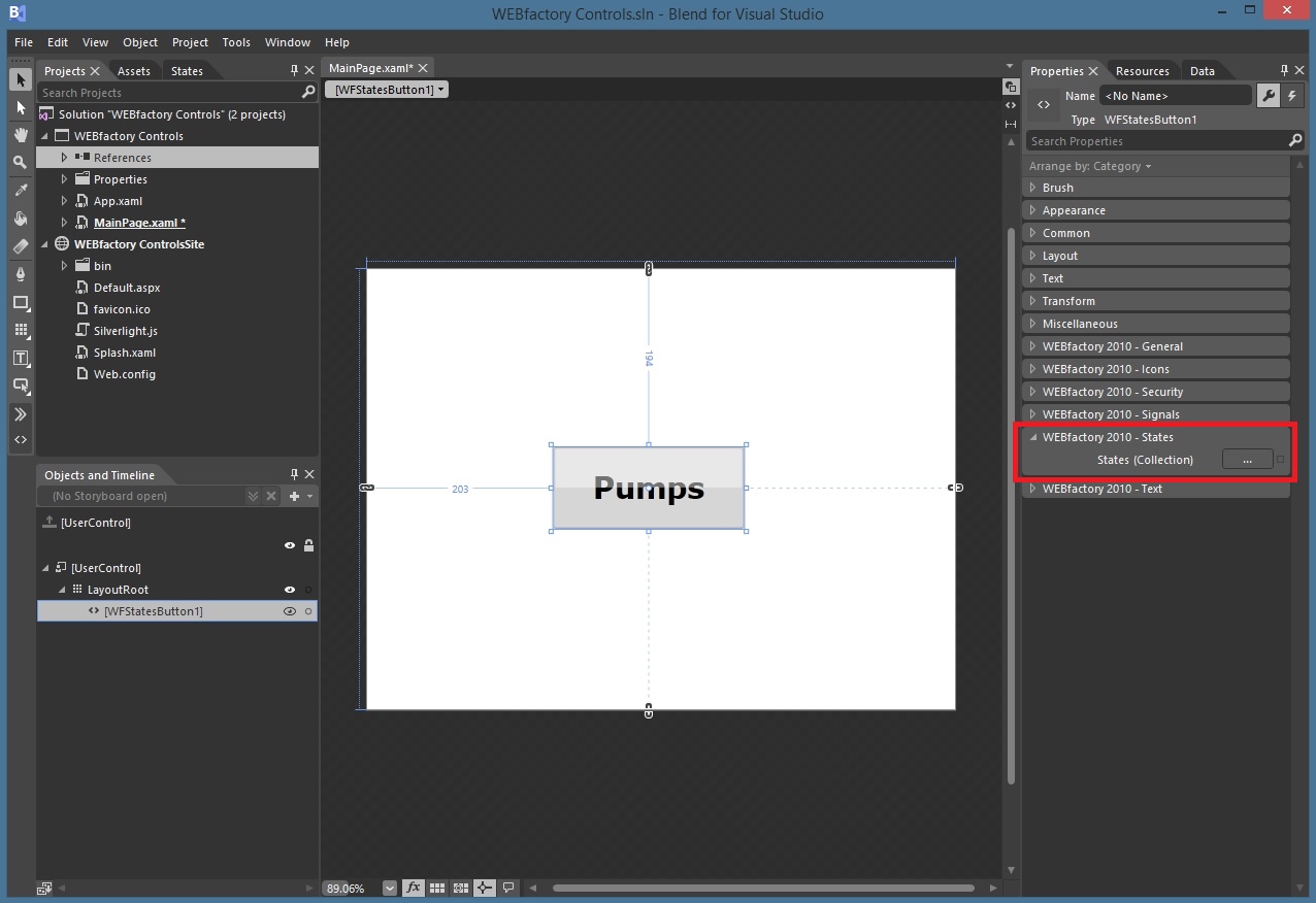
The States Collection Editor button
In the WFStateCondition Collection Editor window, create three different state conditions by clicking the Add button from the bottom-left side of the window. Each state condition will represent the current running Pumps:
The first state, when all three Pumps are running (named ABC).
The second state, when only Pumps A and B are running (named AB).
The third state, when only Pump A is running (named A).
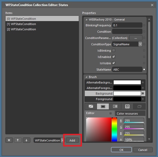
Adding the states
To set up the signal used by the conditions, select the first state and click on the button next to the ConditionParameters (Collection) option.
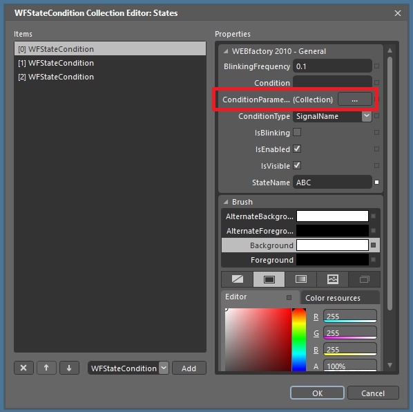
Setting up the signal parameter
In the WFStateConditionParameter Collection Editor, click on the Add button to create a new parameter. Set the ParameterName as Signal and the SignalName to the desired signal. In our use case, the signal used is Setpoint 2.
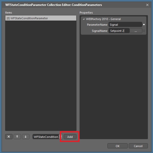
Creating the Signal parameter to be used in the state conditions
Click OK to confirm.
Repeat the same operation for all three WFStateConditions.
Now we need to define the comparator between the signal (defined in the previous step) and the constant value. Because Blend does not provide logical comparators, we need to define our own equation. To achieve this, set the ConditionType for Equation for all three states.
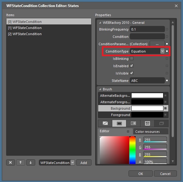
Setting the ConditionType to Equation
In the Condition text field, input the needed equation to apply the binary mask: (Signal & X) == X, where:
Signal is the ParameterName created in the third step (see above) and represents the Setpoint 2 signal.
X is the required decimal value to be interpreted in binary mode. The binary mask will be applied to this value.
For the first state the constant must have the first three bits as 1, meaning that all three Pumps are running. So the constant of the first state will be 7 (111 in binary). Thus the equation will be (Signal & 7) ==7.
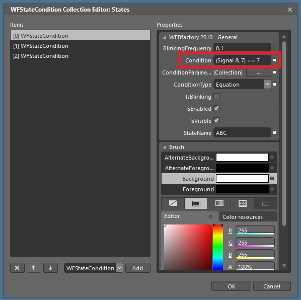
The equation that will enable the first state
For the second state, the constant must have the first two bits as 1, meaning that only pumps A and B are running. So the constant of the first state will be 3 (11 in binary). Thus the equation will be (Signal & 3) ==3.
For the third state, when only one pump is running, the equation will be (Signal & 1) ==1.
IMPORTANT: The order of the WFStateConditions is crucial!
In the WFStatesCondition Collection Editor, the first WFStateCondition has the highest priority. In our case, all signal values have the first bit equal to 1. If the order of the WFStateConditions would have been reversed, the condition for the first state would have been met throughout all the defined WFStateConditions, and because the priority rule, only the first state would have been applied.
Set up each of the state's visual parameters accordingly to the project's requirements. In our use case, we will be using the following model:
For the first state, when all the three Pumps are working, the Background color will be green and the Foreground white.
For the second state, when only Pumps A and B are working, the Background color will be yellow and the Foreground white.
For the last state, when only Pump A is running, the Background color will be red and the Foreground white. Also, the IsBlinking option will be marked for this state, with the AlternateBackground yellow and the AlternateForeground white. This means that the control will blink red and yellow when only one pump is running.
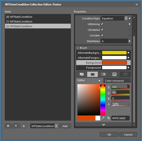
The visual parameters of the third state, with blinking enabled
Run the visualization and use the Ewon by HMS NetworksTest Center to test the control. Use the Setpoint 2 signal and enter the values 7, then 3 and the 1 and notice the changes. The control will display each state depending on the value of the Setpoint 2 signal.
The three states of the WFStatesButton1 control.
When using binary values, not only the exact decimal value used as signal value constant will trigger the associated state. Any other value that, in binary mode, has the same bits equal with 1 will trigger the state.
For example, the second state is triggered when the Setpoint 2 value is 3 (011 in binary mode). The same state will be triggered when the Setpoint 2 value is 11 (1011 in binary mode).