Connector Section
Check out this articles and learn more about the WEBfactory 2010 Studio connectors and how to manage them.
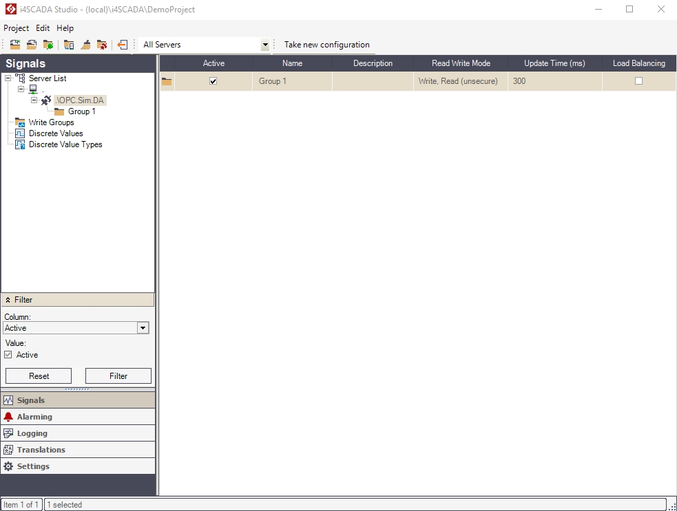
The Connector section is active when a connector is selected in the Signals menu. The Connectors view displays the signal groups containing the available signals for the selected connector. The Connector view is identical for all the connectors available in Ewon by HMS NetworksStudio.
The Connector section
UI Option | Description |
|---|---|
Active | If the Active check-box is marked, the signal group is taken into account when the Ewon by HMS Networksserver is started. |
Name | Signal group name. |
Description | Optional description. |
Read Write Mode | Signal variable read/write mode. Can be:
|
Update Time (ms) | The time interval for the transmission of current process data between connectors and Ewon by HMS Networks servers. |
Load Balancing |
|
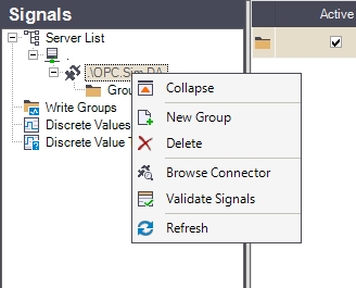
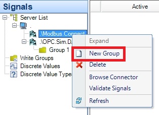
Right-clicking on a Connector in the Signals tree menu will open the contextual menu. The Connector contextual menu provides options such adding or deleting signal groups, browsing the connectors for signals or validating signals.
Connectors contextual menu
UI Option | Description |
|---|---|
Expand/Collapse | Expands/Collapses the Server view menu item, hiding or displaying the available connectors. |
New Group | Allows the user to add a new signal group to the connector. |
Delete | Deletes the selected connector. |
Browse Connector | Opens the Browse Connector dialog, allowing the user to add the signals available to the connector to the Studio project. |
Validate Signals | Opens the Validate Signals dialog, allowing the user to view the invalid or unused signals. |
Refresh | Reloads the list of connectors. |
Important
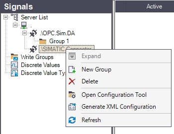
The contextual menu of the SIMATIC connector in the Signals tree menu provides different options!
SIMATIC Connector contextual menu
UI Option | Description |
|---|---|
Expand/Collapse | Expands/Collapses the Server view menu item, hiding or displaying the available connectors. |
New Group | Allows the user to add a new signal group to the connector. |
Delete | Deletes the selected connector. |
Open Configuration Tool | Opens the SIMATIC connector configuration tool (ACCON-AGLink V4 Configuration). |
Generate XML Configuration | Generates an XML configuration based on the settings applied to the SIMATIC connector in Ewon by HMS NetworksStudio. The XML configuration is saved in the database. The Ewon by HMS Networks Server passes the configuration from the database to the connector. When any change has been applied to the SIMATIC connector in Ewon by HMS NetworksStudio, an exclamation mark icon is displayed on the SIMATIC connector in the Signals tree menu. This means that the XML configuration must be generated using the SIMATIC connector contextual menu!  The XML configuration must be generated each time a setting is changed in Studio for the SIMATIC connector! |
Refresh | Reloads the list of connectors. |
Right-clicking on the signal groups listed in the main panel while the a connector is selected will open the contextual menu. The contextual menu allows the user to edit the cell from where the contextual menu was opened, set the read/write mode for the signal group, set the update time for the signal group. It also allows the user to create a new signal group, delete the selected one and refresh the list.
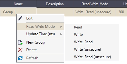
Read / Write mode setting
UI Option | Description |
|---|---|
Edit (context-sensitive) | Edit the property from the currently selected grid cell. |
Read/Write Mode | Set read and write mode for the signal group. Can be:
|
Update Time (ms) | Select the time interval for process data transmission (50 - 60000 ms). |
New Group | Create a new signal group. |
Delete | Delete a signal group. |
Refresh | Update the current view. |
Browse Connector Window
Check out this article and learn more details about the Browse Connector window and how to use the filters in this view.
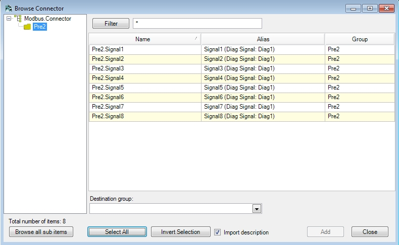
The Browse Connector dialog allows the user to select one or more available signals for the current connector and import them in the Ewon by HMS Networks Studio and place them into the selected signal group. The Browse Connector dialog also allows the user to create a new signal group to add signals in by typing the name of the new signal group directly into the Destination group field.
Browse Connector dialog
The Browse Connector tree menu displays the connector and the available signal structure from the connector.
Connector's tree structure
The filter panel allows the user to filter the available signals using the values of the Name column (of the main view grid) in combination with wildcards.

The Filter panel
The main view of the Browse Connector dialog displays the list of available signals and allows the user to select the desired signals for importing. Multiple selection is supported.
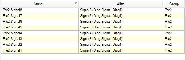
Signal multiple selection panel
UI Option | Description |
|---|---|
Name | The name of the signal in the connector |
Alias | The name of the signal in the OPC server. |
Group | The group to which the signal belongs. This column is visible only when the Browse all sub items button is pressed. |
The Destination group drop-down box allows the user to select the signal group in which to add the selected signals. It also allows the user to create a new signal group, by simply typing the name of the new signal group in the text area. The signal group will be created and the selected signals will be automatically added to it when the Add button is pressed.
The Destination group panel
The Browse Connector dialog allows the user to quickly browse all the connectors items, select all available signals from the main view and invert the current selection. Also the user is able to import the signal description.

Browse connector window - additional options
UI Option | Description |
|---|---|
Browse all sub items | Automatically displays all the available signals and the groups to which they belong in the main view. |
Select All | Selects all the signals available in the main view. |
Invert Selection | Inverts the current selection. |
Import description | Imports the signals description along with the signals. |
Custom Connector
Check out this article and learn more about the WEBfactory 2010 conectors and how to manage them, in a few easy steps.
The Custom Connector's Configuration Panel allows the user to set up an OPC-XML communication between the Ewon by HMS Networks Server and the OPC server using an URL.
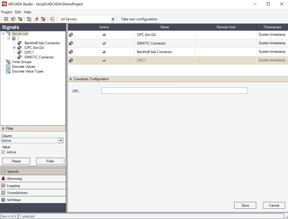
Custom connector configuration panel
When the URL option is used, the Ewon by HMS Networks Server will take this URI from the database and use it to connect to the OPC server via the OPC-XML protocol.
The OPC-XML protocol works over IIS and bypasses the default COM/DCOM communication method. This protocol allows access to remote OPC servers but it is slower than the default COM/DCOM communication method.
If the URL field of the Connector Configuration panel is not used, the connector will use the default COM/DCOM OPC communication method.
Note
The user cannot browse for the URL using the Connector Configuration, the URL address needs to be written or pasted into the URL field. Any change will be applied when the Save button is pressed.
BACnet Connector
Check out this articles and learn all that you need to know about configuring your BACnet Connector on WEBfactory Studio.
The following article provides an overview of the BACnet connector in Ewon by HMS NetworksStudio and describes the following procedures:
Ewon by HMS NetworksStudio offers the possibility of custom configuration for the BACnet Connector. To access the Connector Configuration panel, select the server and select the BACnet connector.
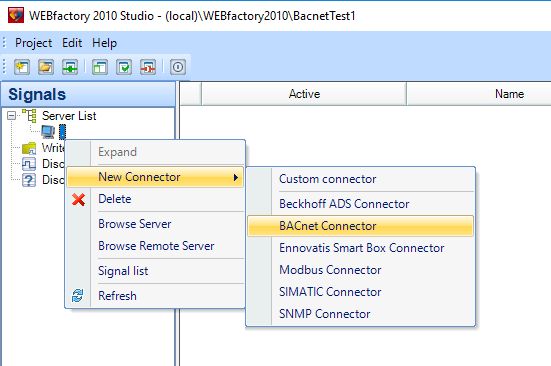
The BACnet Connector inside Ewon by HMS NetworksStudio
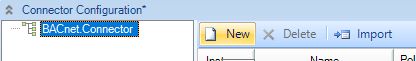
The Connector Configuration panel will appear on screen. The configuration panel allows the parametrization of the connector by using an attributes grid panel.
Importing BACnet device properties
In the Connector Configuration panel, the user can add a Device, by clicking the New button.
New BACnet Device
By selecting the new created Device, the user can add Objects for it, by clicking the New button.
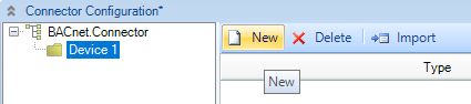
New BACnet Objects
Another option to ad further Devices and Objects to a BACnet Connector, the user can click on the Import button. A pop-up is displayed indicating that the Devices are being searched.
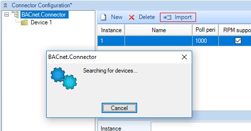
Import button
In the Import BACnet device properties dialog, the user can select the desired properties .
Further on the Ewon by HMS NetworksStudio allows the user to browse the BACnet connector and select the desired properties to assign signals to them.
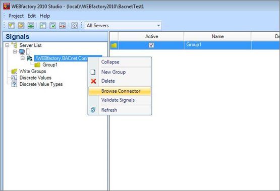
Browsing the BACnet connector
The Browse Connector option (available in the contextual menu of the connector entry in the Server List) will open a browser window. The user has the option to browse for properties and select the desired ones.
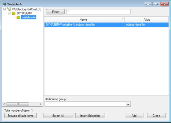
Connector Browser window
One important part of the connector browser is the Filtering option. It allows the user to filter the properties by name. The filtering options uses wildcards for easier input:
*X will filter the names that end with X
X* will filter the names beginning with X
*X* will filter the names that have X anywhere in the name.
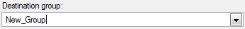
To add the selected properties to the Studio, the properties need to be assigned to a Destination group. This destination group can be created inside the connector browser window by typing the desired name of the new group in the Destination group text field.
The new created group will be listed under the BACnet connector entry in the Server List. Inside the group, the imported properties will have signals assigned automatically. This way the BACnet object can be monitored.
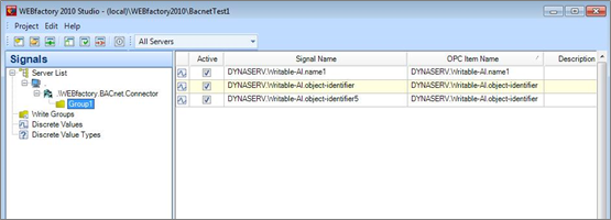
Destination group view
Click here to learn about browsing the BACnet network for devices in different IP address areas.
Validating Signals
The contextual menu of the BACnet connector allows the user to Validate Signals.
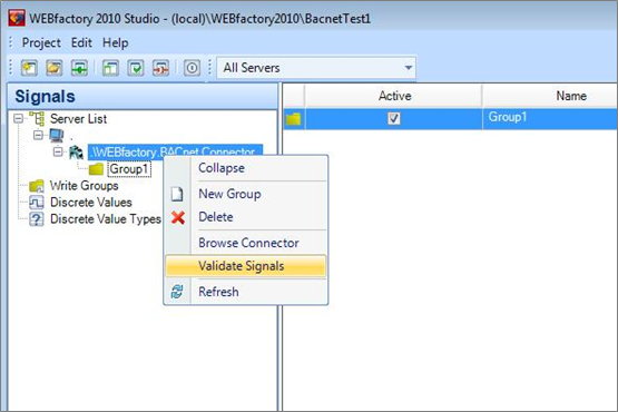
Signal validation
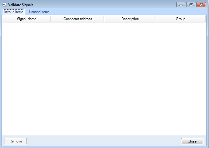
The Signal Validation window displays a list of used invalid items and a list of unused items. The invalid items can be removed from the Studio, and the unused items can be set to be used.
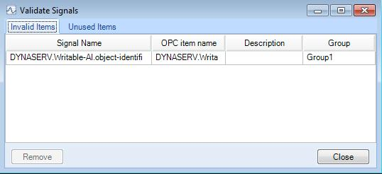
Invalid items panel
To make an unused item to be used, the item must be selected from the Unused Items and assigned to a Destination group.
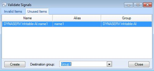
Unused Items panel
The signals created for the BACnet object properties can be exported and imported by selecting the appropriate options in the contextual menu.
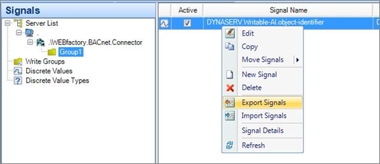
Importing and exporting signals from the BACnet destination group
The format used for importing/exporting is XML.
Starting BACnet Service
The BACnet Service needs to be started before setting up and using any of the BACnet web applications. Ewon by HMS NetworksService Manager lists the Ewon by HMS Networks services including the WEBfactory 2010 BACnet Service.
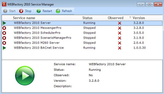
WEBfactory 2010Service Manager
WEBfactory 2010Service Manager is located in WEBfactory 2010 \Tools\Service Manager. Make sure that the WEBfactory 2010 BACnet Service is started before using any of the BACnet web applications!
Cimetrics BACstac Installation
Check out this article and learn how to configure and install the Cimetrics BACstac to create client and server application programs.
The Cimetrics BACstac allows the user to create client and server application programs which use BACnet protocol for communication. The Cimetrics BACstac installer can be found in the 3rd Party folder of the WEBfactory 2010 installation kit.
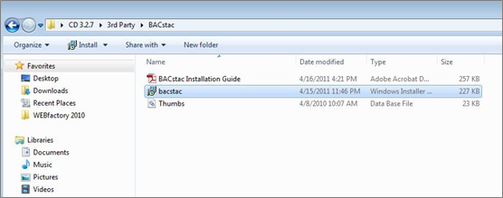
BACstac setup
Run the BACstac installer and follow the installation steps.
Browsing a BACnet device on a different network
Check out this article in order to learn how to browse a BACnet device on a different network, by following the steps described here.
If the i4scada machine is installed in a different network (different IP address area) than the BACnet device, the user is required to organise a set of configurations in order to enable the BACnet connector to browse those devices.
Important
The BACnet device must support BBMD (BACnet Broadcast Management Device). If the BACnet device doesn't support BBMD, a BBMD router is required.
The BACnet device must be configured as follows:
In the BACnet device configuration, activate BBMD.
Insert the IP address of the i4scada host PC that will browse the device.
Further on, organise the following settings on the i4scada host PC, to enable browsing a BACnet device available on a different network:
Open the Cimetrics configurator using the baccfg.bat file. This file should be by default installed under one of these locations:
C:\Program Files (x86)\Cimetrics\BACstac v6.9g
C:\Program Files\Cimetrics\BACstac v6.9g
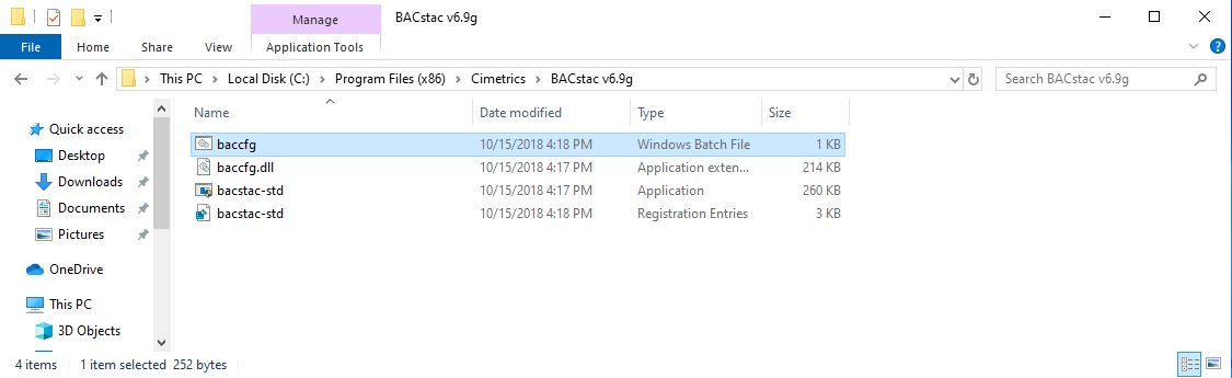
The Cimetrics BACstac configurator on the hard drive
In the Cimetrics BACnetac Port Table window, click the Edit... button to edit the configuration.
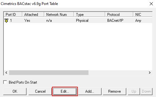
Cimetrics BACnetac Port Table
In the BACnet/IP Port Properties window, click on the Foreign Device tab. Switch to the Foreign Device tab and enter the IP address of the BACnet device (located on the different network) in the Remote BBMD IP Address field. Enter the UDP Port (the default port is 47808). Click OK to confirm.
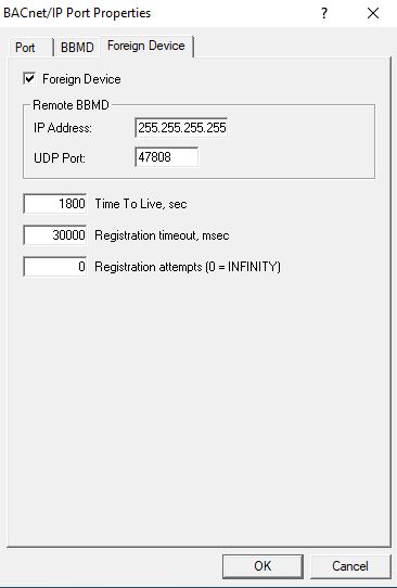
Foreign Device
Click the OK button of the Cimetrics BACnetac Port Table window. A prompt will ask you to restart the BACstac protocol in order to apply the changes. Click Yes.
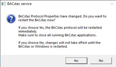
BACstac installer
i4scada Studio will be able now to browse the remote BACnet device.
Using BACnet Logging
Check out this article and learn how to setup the logging for BACnet Windos Service, BACnet Connector and Trace service WTS.
The current article contains descriptive information on:
Setting up BACnet Windows Service logging
Logging the BACnet Windows Service activity can greatly improve the speed and accuracy of debugging and troubleshooting BACnet Windows Service issues in WEBfactory 2010.
The logging for BACnet Windows Service can be easily set up by following the guide below:
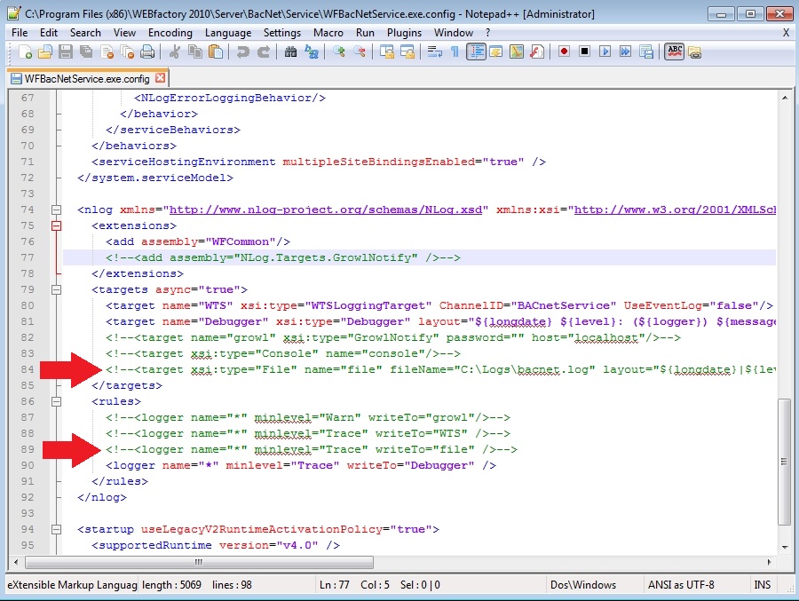
Locate and open the WFBacNetService.exe.config file in any text editor desired. If using a default WEBfactory 2010 installation, the WFBacNetService.exe.config file will be located in C:\Program Files (x86)\WEBfactory 2010\Server\BacNet\Service or C:\Program Files\WEBfactory 2010\Server\BacNet\Service on a x86 machine.
Inside the WFBacNetService.exe.config file, locate an uncomment (remove the
<!--from the beginning of the line and the-->from the end of the line) the target line, line 84:<!--<target xsi:type="File" name="file" fileName="C:\Logs\bacnet.log" layout="${longdate}|${level:uppercase=true}|${logger}|${message}${onexception:EXCEPTION OCCURRED\:${exception:format=tostring}}"/>-->Locate and uncomment (using the same procedure as above) the rule line, line 89:
<!--<logger name="*" minlevel="Trace" writeTo="file" />-->Restart the BACnet Windows Service form the Ewon by HMS NetworksService Manager.
It is recommended to turn off the logging after the troubleshooting session has ended, in order to avoid filling the hard disk space with unnecessary logs.
BACnet Windows Service logging configuration
Taking a closer look at the line specifying the target inside the WFBacNetService.exe.config file will reveal the configuration options for BACnet Windows Service logging:
The fileName attribute sets the path and the name of the log file. The user can alter it's value and specify any existing folder and file name.
The rule line provides the option to configure the logging level:
The minlevel attribute sets the minimum level for logging. The user can set it to Trance, Warn or Error.
Setting up BACnet Connector configuration logging
The logging for BACnet Connector must be manually enabled using the Registry Editor tool available in any Windows OS. The BACnet Connector registry settings location depends on the operating system:
If WEBfactory 2010 is installed on a x64 machine, the BACnet Connector registry settings are available at
HKEY_LOCAL _MACHINE\SOFTWARE\Wow6432Node\WEBfactory\BACnet\1.0.If WEBfactory 2010 is installed on a x86 machine, the BACnet Connector registry settings are available at
HKEY_LOCAL _MACHINE\SOFTWARE\WEBfactory\BACnet\1.0.
By default, the following registry values are available for the BACnet Connector key:
Value | Type | Details |
|---|---|---|
MessageLevelMask | DWORD | A 32 bit mask specifying logging that is produced by BACnet Connector and that is subsequently being submitted into the WTS. MessageLevelMask bits for BACnet Connector:
Finding the best log file detail balance means a compromise between:
Full logging rate can be in the range of tens of thousands lines per second and can cause problems with Cimetrics toolkit. Therefore implicit mask should have bits 0, 1 and 2 set. |
ToolBoxInstalled | DWORD | Either 0 or 1. Specifies if the BACnet ToolBox is installed on the system. |
VB6DataTypes | DWORD | Either 0 or 1. Controls data type transformation for VB6. |
To enable the logging for BACnet Connector, the user must manually add the following value:
Value | Type | Details |
|---|---|---|
ConfigXMLSavePath | STRING | Specifies the path where the XML configuration received in Init method would be stored. This XML configuration is stored prior to checking of its correctness. Tabs and newlines are inserted into stored configuration just as well. |
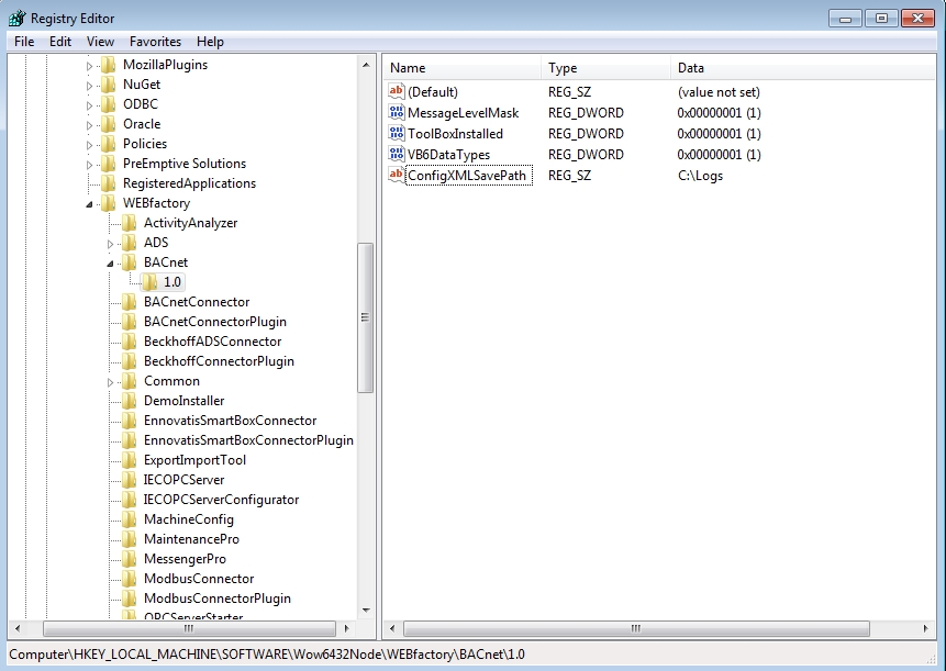
The BACnet Connector registry settings with configuration logging enabled
Setting up Ewon by HMS Networks Trace Service (WTS) logging
Setting up WTS logging for single log file group
Using the following method, the user can enable logging for multiple Channels (tools and services provided by WEBfactory 2010) that will be saved on disk in the same log file.
To log each channel events in separate files, follow the guide in the sub-section below.
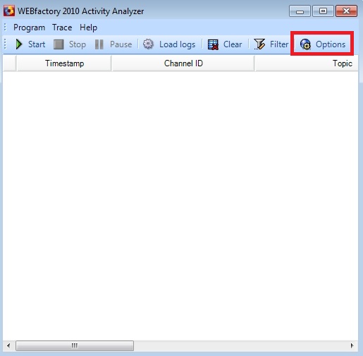
To enable Ewon by HMS Networks Trace Service logging, the user can use the WEBfactory Activity Analyzer tool and activate the File Writer in order to store the logs on the hard drive:
Open the WEBfactory ActivityAnalyzer and click the Options button.
In the Options window, click on the File writer tab. Check the Enable file writer checkbox to write the logs to the disk.
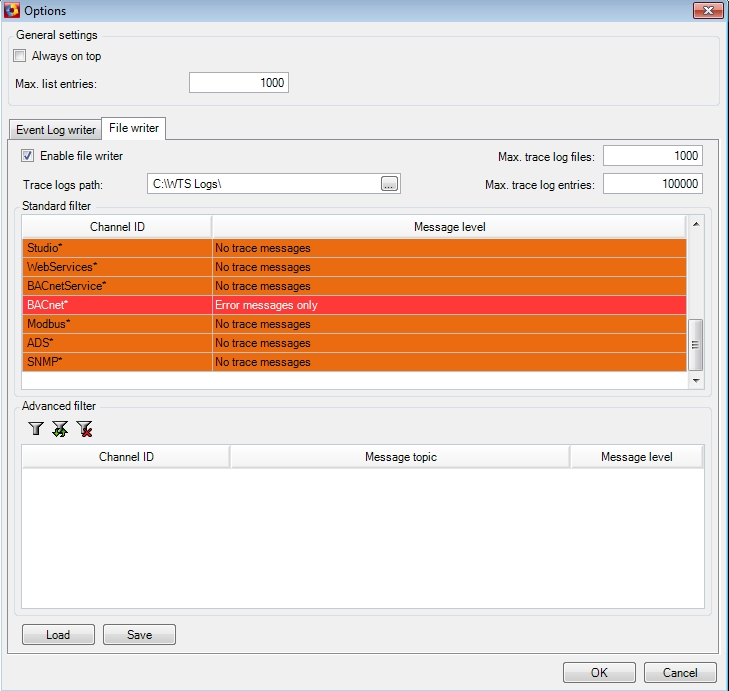
Set the Trance logs path to an existing folder on the hard disk.
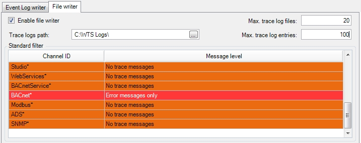
Set the Max. trace log files (the maximum amount of log files to be stored) value.
Set the Max. trace log entries (the maximum size on disk - by default in MB - of all the stored log files) value.
Set the Standard filter (the logging filter) for the desired channel.
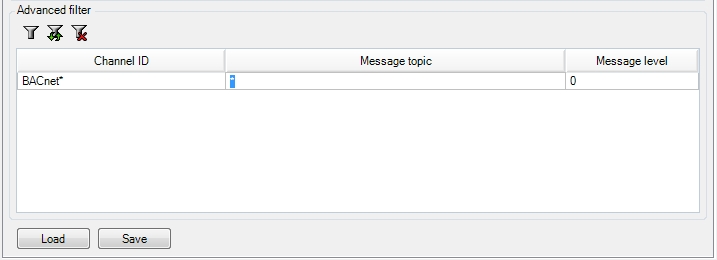
Optional, the user can set and Advanced filter and define the Channel, Message topic and Message level manually.
For more control over the logging options, the same settings can be accessed in the Registry Editor. The key location depends on the operating system:
On x64 version of operating system, WTS registry settings are located at:
HKEY_LOCAL _MACHINE\SOFTWARE\Wow6432Node\WEBfactory\WTS\1.0\LoggerKeys\FileWriterOn x86 machines, the Wow6432Node is missing, so the WTS registry settings would be located at:
HKEY_LOCAL _MACHINE\SOFTWARE\WEBfactory\WTS\1.0\LoggerKeys\FileWriter
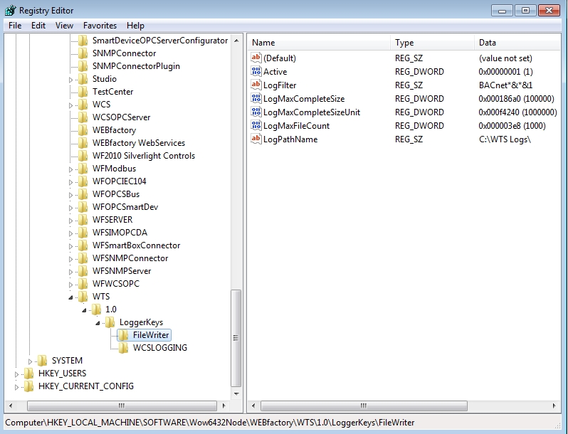
The FileWriter key hosts the following values:
Value | Type | Details |
|---|---|---|
Active | DWORD | Either 0 or 1, specifying if log group is active or not. Only active log groups are being logged. |
LogFilter | STRING | Specifies filtering for messages. For BACnet logging filter would be BACnet*&amp;*&amp;FFFFFFFF. |
LogMaxCompleteSize | DWORD | Specifies the maximum number of bytes in all log files that exist in any moment. If log file currently being written exceeds in size LogMaxCompleteSize or LogMaxFileCount bytes, than log file is closed and new log file with new, higher number is started. |
LogMaxCompleteSizeUnit | DWORD | Specifies unit size for LogMaxCompeteSize value. In example above, LogMaxCompleteSizeUnit is 1 MByte, and as LogMaxCompleteSize is 100 dec., size of all undeleted log files is 100 MBytes. The size of a single individual log file is 20 times smaller because LogMaxFileCount is 20, that is 5 MBytes. If LogMaxCompleteSizeUnit is missing, than LogMaxCompleteSize is in bytes. |
LogMaxFileCount | DWORD | Specifies the maximum number of files in a file group. When the maximum number of files in a file group is exceeded, the oldest file (the file with smallest number) is deleted. The content of the log files is never overwritten. New files are being added and oldest files are being deleted, so the count of the files that exist in any moment does not exceed LogMaxFileCount. |
LogPathName | STRING | Specifies a textual prefix of path name for each file inside the file group. The file path name is generated by adding a prefix, file number, dot and log file extension ([Prefix][FileNumber].log). For example: LogOne_000000001.log, LogOne_000000002.log, LogOne_000000003.log, LogOne_000000004.log, LogOne_000000005.log, etc. |
Any number of sub-keys (like FileWriter) can exist for LoggerKeys (at
HKEY_LOCAL_MACHINE\SOFTWARE\Wow6432Node\WEBfactory\WTS\1.0\LoggerKeysorHKEY_LOCAL_MACHINE\SOFTWARE\WEBfactory\WTS\1.0\LoggerKeys).This way, multiple file groups can be set up for logging.
Setting up WTS logging for additional log file groups
By default, Ewon by HMS Networks Trace Service logs all the selected channels in the same log file groups. Setting up WTS logging from the Registry Editor allows the user to configure multiple log file groups to be written, each for a separate channel. This can be helpful in order to avoid searching through all the logged information for a specific channel.
To create a separate log file group for logging, for example, the BACnet channel, the user has to manually create a sub-key under the FileWriter key and create the needed values.
An example of a secondary file group for logging would be:
[HKEY_LOCAL_MACHINE\SOFTWARE\Wow6432Node\WEBfactory\WTS\1.0\LoggerKeys\ExampleFileGroup]
"LogPathName"="C:\\SecondFileGroup\\"
"LogMaxCompleteSize"=dword:00000064
"Active"=dword:00000001
"LogMaxFileCount"=dword:00000014
"LogFilter"="BACnet*&*&1"
"LogMaxCompleteSizeUnit"=dword:000f4240
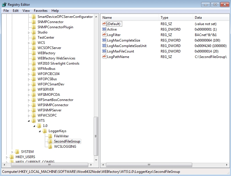
The key and values can be manually created inside the Registry Editor or can be added using a .reg script.
Registry script example: SecondFileGroup.reg (zip archive)
The script above can be edited and used to add the desired secondary file group for logging a channel.
The LogPathName directory structure must exist on the disk before using it.
WTS must be restarted for the registry settings changes to take effect!
BACnet Connector Online/Offline Device Detection
Learn more details about the BACnet Connector Online - Offline Device Detection parameters, by reading this article.
The period of detection for online/offline devices is specified in WhoIsPeriod parameter in the <Devices> section of XML configuration file. The unit is millisecond.
Using this WhoIsPeriod, the WhoIs BACnet broadcast is sent. The broadcast is limited to devices between the lowest and the highest Device-object ID in the XML configuration. The network number for broadcast is specified in Network parameter in the <Devices> section of XML configuration.
After broadcasting the WhoIs message, the BACnet connector waits for the devices to respond with the IAm message. The length of the waiting period is specified in WhoIsReplyWait parameter in <Devices> section of XML configuration. The unit of the waiting period is millisecond.
After the waiting period has passed, all devices that did not responded are marked as nonexistent/offline.
If the presence of the BACnet hardware device is detected for the very first time or if the device is detected after being temporarily nonexistent/offline, the complete initialization of the device access takes place.
The initialization of the device access includes the reading the list of all objects inside the device and the comparison of the object list to objects specified in XML configuration.
The COV subscription of all objects and properties takes place. Object properties are re-read immediately.
BACnet Connector COV lifetime and resubscription
For more details about the BACnet Connector COV lifetime and resubscription check out this article.
The lifetime of the COV subscription is specified in the COVPeriod in the <Device> section of the XML configuration.
The COV resubscription takes places automatically for all devices with half of the period specified in COVPeriod parameter in each <Device> section of the XML configuration. The unit of COV period is in milliseconds.
Some BACnet devices send values of relevant properties to the BACnet connector while being subscribed to COV and some devices do not send initial values. Therefore the COV1Read parameter in <Device> section of the XML configuration instructs the BACnet connector to read the property values once, even for those properties which are subject to COV subscription.
BACnet Whitepaper [PDF]
Here is the BAcnet Whitepaper documentation to help you understand an issue, solve a problem, or make a decision.
BACnet Protocol Implementation Conformance Statement [PDF]
To make sure that BACnet meets your requirements check out the Protocol Implementation Conformance Statement here.
Read the BACnet Protocol Implementation Conformance Statement, here.
Beckhoff ADS Connector
Check out this article and learn more details about the WEBfactory 2010 Beckhoff ADS Connector.
The Beckhoff ADS Connector Configuration panel allows the user to configure the devices using this connector and the signals associated with the devices. The Connector Configuration panel is split in two tabs: Devices and Signals.
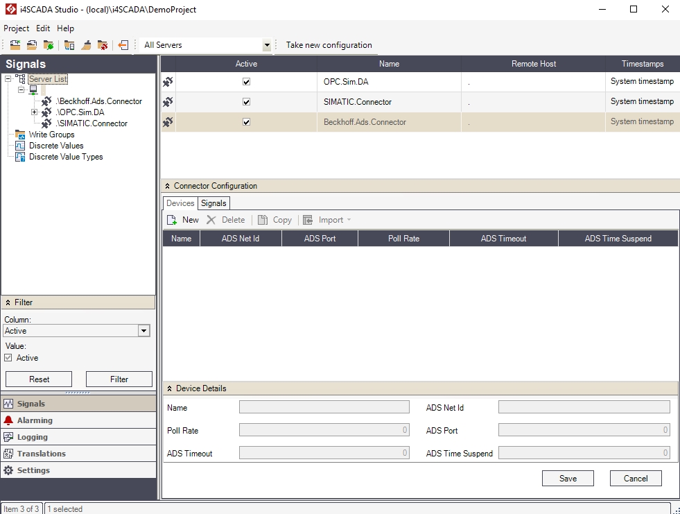
Beckhoff ADS Connector configuration panel
In the Devices tab you can have up to 200 devices linked using Beckhoff ADS Connector.
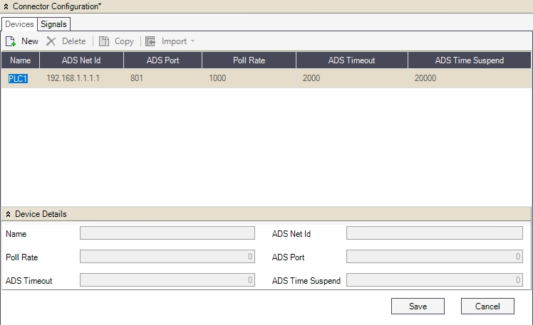
The Devices tab
The top menu allows the user to add, delete and copy devices, but also import configurations from TPY files for the selected device.
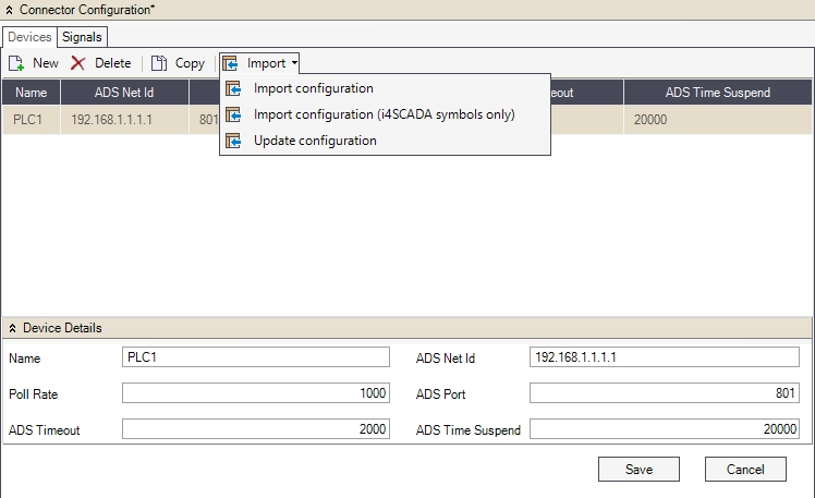
Import options
UI Option | Description |
|---|---|
New | Adds a new device. |
Delete | Deletes the selected device. |
Copy | Copies the selected device one or more times. This is useful when having multiple devices in the same ADS network, using the same symbol lists. |
Import | Imports configurations.
|
The devices grid of the Connector Configuration panel displays the devices and their parameters in the grid's columns.
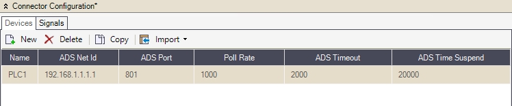
The Devices tab - grid view
The available parameter columns are:
Name: The unique name of the device. This serves as a device name for SignalPrefix.
ADS Net Id: The device address inside the ADS network.
ADS Port The: ADS communication port of the device.
Poll Rate: The time interval (in milliseconds) for polling the ADS device.
ADS Timeout: The timeout for communication operations (in milliseconds).
ADS Time Suspend: Suspend time after communication errors.
The same parameters are available for editing in the Device Details panel.
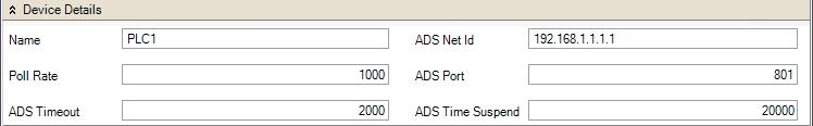
The Device details panel
The Signals tab contains all the signals of the devices connected via the Beckhoff ADS Connector.
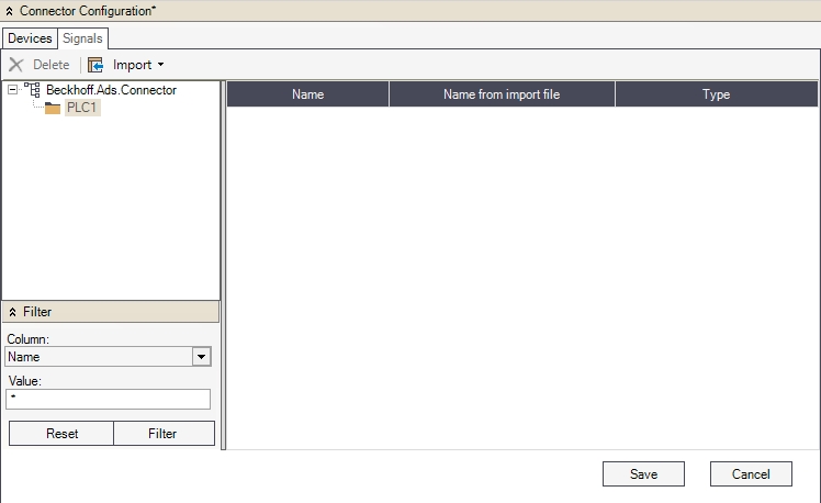
The Signals tab
The top menu allows the user to delete signals and import configurations from TPY files for the selected device.
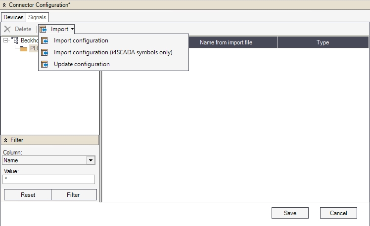
The Import options
UI Option | Description |
|---|---|
Delete | Deletes the selected device. |
Import | Imports configurations.
|
The Signals pane tree menu allows the user to navigate between the connected devices and display the signals in the signals grid, individually, for each device.
The Filter panel allows the user to filter the signals displayed in the signals grid using the Columns of the signals grid and their Values as filter criteria.
The signals grid of the Connector Configuration panel displays the signals with their name, original name and type in the grid's columns. The available parameter columns are:
Name: The name of the signal in the project.
Name from import file: The original name of the signal in the TPY file.
Type: The type of the signal's value. Can be INT, REAL or STRING.
System Requirements
Before starting to work with the Beckhoff ADS Connector on WEBfactory 2010, please read the system requirements article.
Compared to the WEBfactory 2010 basic system, the WEBfactory 2010 Beckhoff ADS Connector has advanced requirements regarding the minimum configuration of the hardware and software on your system.
Read the advanced requirements concerning the hardware and software below:
Beckhoff ADS Connector System Requirements | |
|---|---|
Supported PC operating systems | Windows XP SP3 Windows Server 2003 SP2 Windows Vista SP1 Windows 7 |
Supported TwinCAT version | TwinCat v2.6 |
Supported Devices | Beckhoff Bus-Coupler Series BK90xx Beckhoff Embedded-PC-Series CX90xx |
Representable PLC data in the ADS -Connector | Access to TwinCAT-Variables per symbol name |
Data format for import functions | *.tpy |
Filtering Ewon by HMS Networks items using the Beckhoff PLC software
Check out this article and learn how to filter items using the WEBfactory 2010 Beckhoff PLC software.
In order to be able to filter Beckhoff PLC items when importing them in Ewon by HMS NetworksStudio, a special comment must be added in the Beckhoff PLC software, next to each desired item.
In the following example, the process of commenting code in Beckhoff PLC software and importing filtered items in Ewon by HMS NetworksStudio will be described in a step-by-step manner. The Beckhoff PLC software used in this guide is TwinCAT PLC Control.
Use case
For demonstration purposes, we will assume we have a list of 10 variables in the PLC program, and we need to automatically filter 5 variables to be imported in Ewon by HMS NetworksStudio (using the Import configuration (Ewon by HMS Networks symbols only)).
Use case solution
In the TwinCAT PLC Control software (or any other Beckhoff PLC software), open the desired PLC program.
The example PLC program in TwinCAT PLC Control
The demo program contains 10 variables. The first 5 represent signals that we don't need in Ewon by HMS NetworksStudio. The last 5 variables need to be imported in the Ewon by HMS NetworksStudio Beckhoff connector configuration, and from there, in Ewon by HMS NetworksStudio Beckhoff connector as Ewon by HMS Networks signals.
In order to achieve automatic filtering at import, a special Ewon by HMS Networks comment needs to be placed inline with the variable to be imported. The next step describes the procedure.
Place the (*~ (Ewon by HMS Networks : 1 : enabled for WF ) *) comment next to the variables that need to be imported in Ewon by HMS NetworksStudio (as .tpy configuration).
The items with comments will be filtered in by Ewon by HMS NetworksStudio
The variables can also be imported with custom name and custom description. This will require additional parameters in the comment syntax:
(*~ (Ewon by HMS Networks  : 1 : enabled for WF
Name = Example_signal_name
Description = Description of the Signal_name)*)
The same PLC program code with custom names and comments will look like this:
The comments containing custom signal name and description
The custom name will be available in Ewon by HMS NetworksStudio as Signal name and the custom description as Signal description.
From the menu bar, select Project and click on Build (or press Ctrl+F8). The program will be built and the necessary files can be located in the program's folder. Locate the .tpy file in the build folder.
The .tpy file is needed for importing Beckhoff items in Ewon by HMS NetworksStudio
In Ewon by HMS NetworksStudio, select the Ewon by HMS Networks .Beckhoff.Ads.Connector and open the Connector Configuration panel. Select the Beckhoff device to import the configuration to, or create a new device by clicking the New button.
The Beckhoff device to which the items will be imported to
With the desired Beckhoff device selected, click on the Import drop-down menu and select Import configuration (Ewon by HMS Networks symbols only).
Importing filtered items only from the configuration
Select the .tpy file from the Beckhoff PLC program build folder and click Open. Ewon by HMS NetworksStudio will display a dialog confirming the import of the 5 signals from the configuration. The signals are now available in the Signals tab of the Connector Configuration panel. The connector can new be browsed and the signals used in Ewon by HMS NetworksStudio.
The newly imported signals in the Beckhoff ADS connector.
If custom names and descriptions are available for the imported items, the signals resulting from the imported items will have the custom name displayed as Alias and the custom description as Description.
Setting up the Beckhoff ADS Connector on a local 64bit system
Check out this article and learn how to set up the Beckhoff ADS Connector on a local 64bit system,.
Installing the Beckhoff ADS Connector
To setup and use the Beckhoff ADS Connector on a local 64 bit system, the following steps must be executed:
Install TwinCAT Engineering Station, x64 version (Tc211x64Engineering_2110_2034.exe) on the machine where the Beckhoff ADS Connector will run (where WEBfactory 2010 is installed).
The TwinCAT Engeneering Station, versions 2.11.x or 3.1.x for x64 needs to be installed on the same machine running the WEBfactory 2010 and Beckhoff ADS Connector. If the software is uninstalled from that machine or installed on a different one, the functionality of the Beckhoff ADS Connector will be limited.
After installation, navigate to C:\TwinCAT\ADS API\TcAdsDll\ and copy the following dll files:
AdsDll.dll
TcAdsDll.dll
Paste the dll files in C:\Program Files (x86)\WEBfactory 2010 \Server\Connectors\Beckhoff ADS.
Copy the dll files to the Beckhoff ADS directory in WEBfactory 2010 installation folder.
The next part of the configuration will take place in Ewon by HMS NetworksStudio.
Beckhoff ADS Connector configuration
Navigate to Server List, select the desired server and right-click to open the contextual menu. Select New Connector > Beckhoff ADS Connector.
A new Beckhoff ADS Connector is added. The Connector Configuration tabs will be displayed.
The Connector Configuration section is divided in two tabs:
Devices
Signals
In the Devices tab you can have up to 200 devices linked using Beckhoff ADS Connector.
To add a new device, click the New button in the toolbar.
The Devices tab also offers the possibility to copy an existing device. This is useful when having multiple devices in the same ADS network, using the same symbol lists.
The Devices configuration table has the following parameters:
Name - unique device name. This serves as a device name for SignalPrefix
ADS Net Id - the device address inside the ADS network
ADS Port - the ADS communication port of the device
Poll Rate - the time interval (in milliseconds) for polling the ADS device
ADS Timeout - timeout for communication operations (in milliseconds)
ADS Time Suspend - suspend time after communication errors
The Devices configuration table has the following parameters:
Import the complete TPY configuration
Import the TPY configuration partially - only Ewon by HMS Networks symbols only
Update the existing list of symbols from the Beckhoff ADS Connectors.
Remove invalid symbols from the current symbol list
Add unused symbols to the symbol list
The symbols can be deleted manually, in order to optimize the communication load.
In the Signals tab, all signals of the PLCs connected via Beckhoff ADS Connector can be seen. The Signals tab offers the same import methods as the Devices tab, and allows the user to manually delete signals.
The Signals tab offers the same import methods as the Devices tab, and allows the user to manually delete signals.
The Beckhoff ADS Connector provides special signals used to monitor the connection with the connected ADS device (ex. PLC1.WatchDog).
This signals need to be declared only as Ewon by HMS Networks signals within the Beckhoff ADS Connector corresponding signal group. This signals are updated by the Beckhoff ADS Connector once per second, counting the number of seconds since the last successful communication.
If the time to access a device is 10 seconds, the associated WatchDog signal will have the value 10. If the communication with the device is possible, the value of the signal will be 0.
Browsing the Beckhoff ADS Connector
To add signals to the new group, right-click on the Beckhoff ADS connector and select Browse connector.
The Browse connector window allows the user to select signals from the Beckhoff ADS device and assign them to signal groups. The signal groups can be created like mentioned above or can be created here, by typing a new signal group name in the Destination group text field.
The Browse connector window features multi-selection tools like Select All, Invert Selection, Browse all. Besides the signal handling tools, the Browser connector window allows the user to import the signals with their descriptions, by checking the Import description option. The description of a signal will appear in the description field, if available.
To add signals to the signal groups, select the desired signals, check or uncheck the Import description option and specify a Destination group (if no Destination group available, create one by typing the name in the text field. The application will ask to confirm the creation of a new group).
SNMP Connector
The scope of these articles is to guide you through your work with the SNMP Connector on WEBfactory 2010 Studio.
The SNMP Connector Configuration panel allows the user to configure the machine connections using this connector and the data output associated with the machine connections.
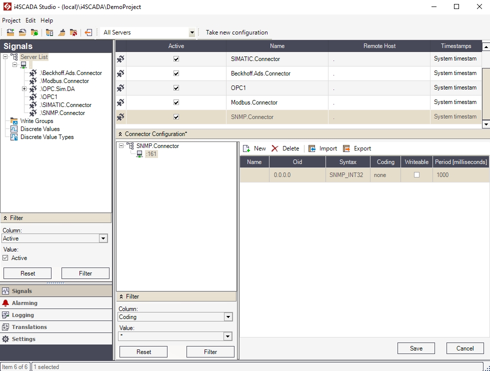
The SNMP Connector configurations panel
The tree menu will display the SNMP machine connections under the SNMP connector.
The Filter panel allows the user to filter the items displayed in the main view grid using the Columns of the main view grid and their Values as filter criteria.
The SNMP Connector Configuration panel menu allows the user to add a new object, delete the selected object and import/export configurations.
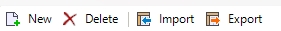
Toolbar options
UI Option | Description |
|---|---|
New | Adds a new SNMP device or signal. |
Delete | Deletes the selected object. |
Import | Imports a configuration from a SNMP configuration file. |
Export | Exports the configuration to a SNMP configuration file. |
Depending on the selected object in the tree menu, the main view of the SNMP Connector Configuration panel can display either the Machine Connections view, where all the SNMP machine connections are listed, or the Data Output view, where all the data output of a machine connection are listed.
Machine Connections view
In this view, the main grid of the Connector Configuration panel displays the available SNMP machine connections.
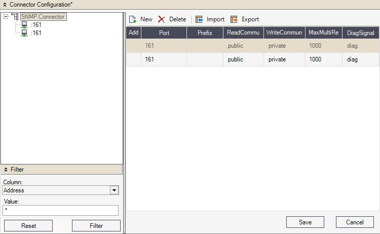
Machine connections view
UI Option | Description |
|---|---|
Address | The network address (IP) of the machine that holds the device. |
Port | The network port to use. The default value is 161. |
ReadCommunity | The community name authorized to read the data from the device. This was set up before, in the SNMP Service. |
WriteCommunity | The community name authorized to write the data from the device. This was set up before, in the SNMP Service. |
Prefix | The prefix of the machine connection. |
DiagSignal | The diagnose signal. |
MaxMultiRead | The maximum number of read commands in one packet. |
Data Output view
In this view, the main grid of the Connector Configuration panel will display the available signals for the selected SNMP machine connection.
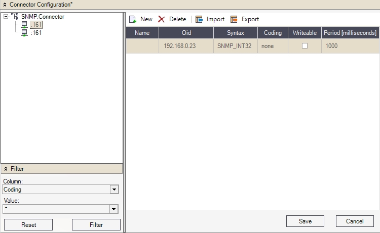
Data output view
UI Option | Description |
|---|---|
Name | The name of the signal (data output). |
Oid | Object Identifiers uniquely identifying manged objects in a MIB (Management Information Base: a collection of information organized hierarchically) hierarchy. |
Syntax | The method of interpreting the data. Can be:
|
Writable | If checked, the data can be writable. |
Period (milliseconds) | The read periodicity of the data, expressed in milliseconds. |
Setting up the Simple Network Management Protocol (SNMP) on the Windows machine
Learn how to set up the Simple Network Management Protocol SNMP on your Windows machine.
The SNMP connector is a Ewon by HMS Networks connector that uses the Simple Network Management Protocol (SNMP) to connect to various devices located on a Windows machine or remote non-Windows devices (routers, switches, hubs, etc.).
In order to use the SNMP Connector, the Simple Network Management Protocol (SNMP) must be enabled in Windows, and the SNMP service must be configured to work with the SNMP Connector in Ewon by HMS NetworksStudio.
To enable the Simple Network Management Protocol (SNMP) on a Windows machine, follow the next steps:
Using the Start menu search box, type "Turn Windows features on or off" and open the Windows Features dialog.
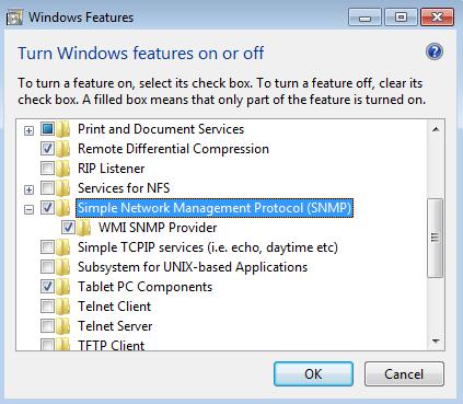
Turn Windows features on or off
Go to Simple Network Management Protocol (SNMP) and mark both Simple Network Management Protocol (SNMP) and WMI SNMP Provider for installation. Select OK to confirm.
Now that the SNMP feature is on, we need to configure the SNMP service to work with the SNMP Connector. In the Start menu search box, enter services.msc and open the Services window.
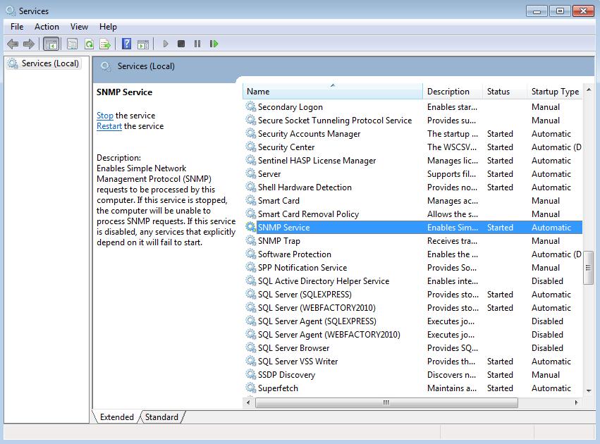
Services window
Find the SNMP Service and double click it to edit its properties. In the new SNMP Service Properties window, go to the Security tab.
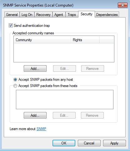
SNMP Service Properties window
Note
The SNMP packets can be accepted from any host or from hosts defined by IP/IPX addresses
The security features of the SNMP Service must be set up in order to give access to the SNMP Control of Ewon by HMS NetworksStudio to the data passed by this service. To do so, we need to create a Community that has privileges to Read and/or Write the data received from the desired component via the SNMP Service. In the Accepted community names section, click on the Add button.
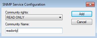
SNMP Service Configuration
Select a Community right from the drop-down combo box and give a name to the new community (for tutorial purposes, the name will be readonly).
Click on Add to add the new community and confirm by pressing OK in the SNMP Service Properties window.
Tip
Later on, in Ewon by HMS NetworksStudio, we will use this community name in the SNMP Connector to have access to read the components data via this protocol.
Now the SNMP Service is enabled and configured on the machine and the SNMP Connector in Ewon by HMS NetworksStudio can communicate with any device that supports the SNMP protocol.
Tip
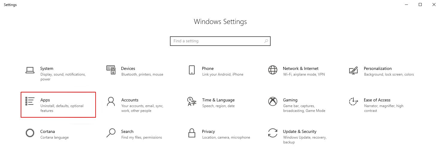
If you have Windows 10 1809 OS build 17763.xxx, the SNMP Settings can be enabled, as follows:
Using the Start menu search box, type "Settings" and open the Windows Settings panel. Click on the Apps option.
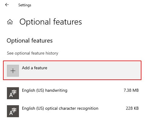
In the Apps & features window click on Optional features.
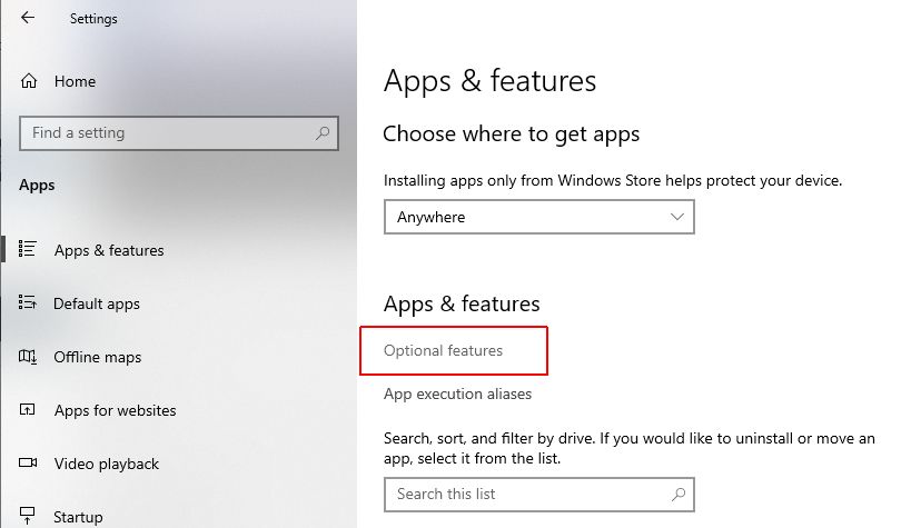
In the Optional features window click on the Add feature button.
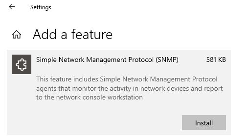
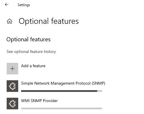
Scroll to the listed features and identify the following features:
Simple Network Management Protocol (SNMP)
WMI SNMP Provider
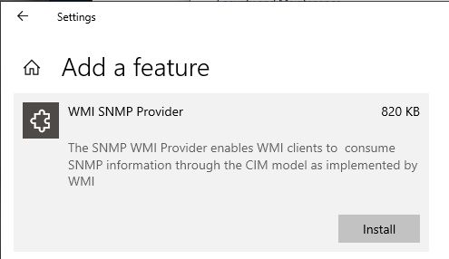
Install both of these features.
Using the SNMP Connector
Check out this article and learn how to use the SNMP Connector on WEBfactory 2010 Studio application.
This tutorial will exemplify the creation of a SNMP Connector and the setup of the connector in order to receive data.
We will use the SNMP Connector inside Ewon by HMS NetworksStudio to connect to the local machine and get the number of running processes, using the OID value obtained from a MIB browser.
Setting up the SNMP Connector in Ewon by HMS NetworksStudio
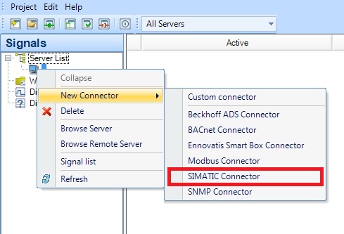
In WEBfactory 2010Studio, go to Server List inside the Signal tab. Select the server from the Server List and right click in the right panel to create a New Connector; select SNMP Connector.
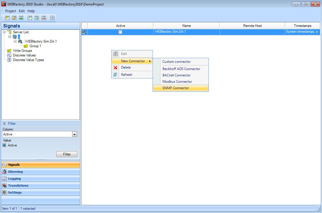
Creating a New Connector in Ewon by HMS NetworksStudio
The new connector will be listed in the connectors list. If the Demo Project is installed, the new SNMP Connector should be listed under the Ewon by HMS Networks .Sim.Da.1 connector. The new SNMP Connector that we just created will be named Ewon by HMS Networks .SNMP.Connector.
Activate the new SNMP Connector by checking the Active box from the Server View grid.
By default, the Connector Configuration panel will be opened upon creating a new SNMP Connector. To create a machine connection in the SNMP Connector, select New from the Connector Configuration panel.
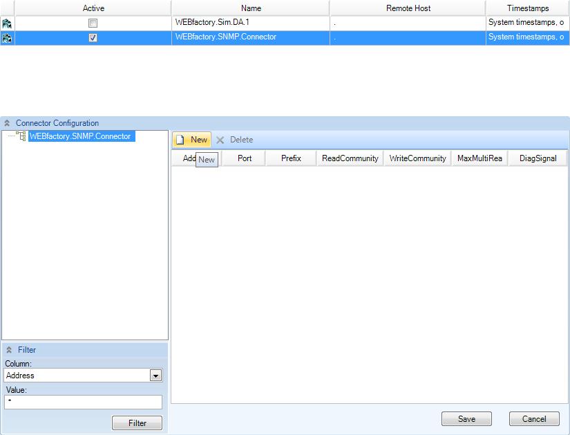
Connector Configuration panel
The new connection will be available in the tree structure, and the connection properties will be displayed in the properties table.
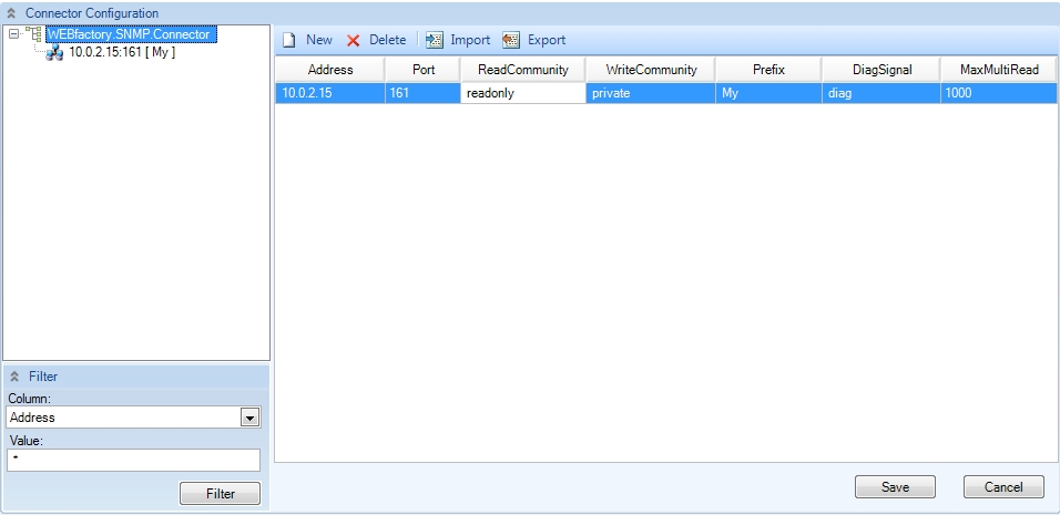
The new connection and its properties
Enter the target machines IP address (obtained by running the
ipconfigcommand in Command Prompt) in the Address field. For tutorial purposes, enter your machine's own IP.Enter a prefix in the Prefix field. For this example, enter My as prefix.
Enter the ReadCommunity and the WriteCommunity as configured in the SNMP Service. In our Setting up the SNMP tutorial, the ReadCommunity was set up with the name readonly).
Press Save to save this settings.
Now the new connection from the SNMP Connector is targeting the local machine.
Next we will address to a specific data output from the local machine, by using an OID. For tutorial purpose, we will use the 1.3.6.1.2.1.25.1.6.0 OID number, which refers to the number of current running processes.
To create a data output connection, select the machine connection defined earlier and click on the New button from the top bar.
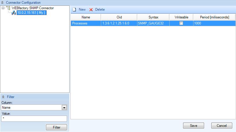
New device connection
Enter the name of the data output in the Name field. For this example, we will use Processes, as the device in our case is the number of processes.
Enter the 1.3.6.1.2.1.25.1.6.0 OID number in the OID field. This will address to the number of current running processes.
In order to be able to display the data from the targeted data output, select a syntax option from the Syntax menu. In this example, the correct syntax for displaying the number of current running processes is SNMP GAUGE32.
Leave the Writeable check-box unmarked, as the number of processes cannot be written, but only read.
For the Period property, leave the value at 1000 milliseconds.
Click Save to save the current changes.
Setting up the signal for the SNMP Connector
Now the SNMP Connector is configured and connected to a data output. In order to see the actual data output, we need to create a signal for our data output.
In order to create a new signal in the Ewon by HMS Networks .SNMP.Connector, we need to create first a new signal group in our connector.
Select the connector from the Signal tab > Server List > server and right click in the empty pane from the right side. Select New Group.
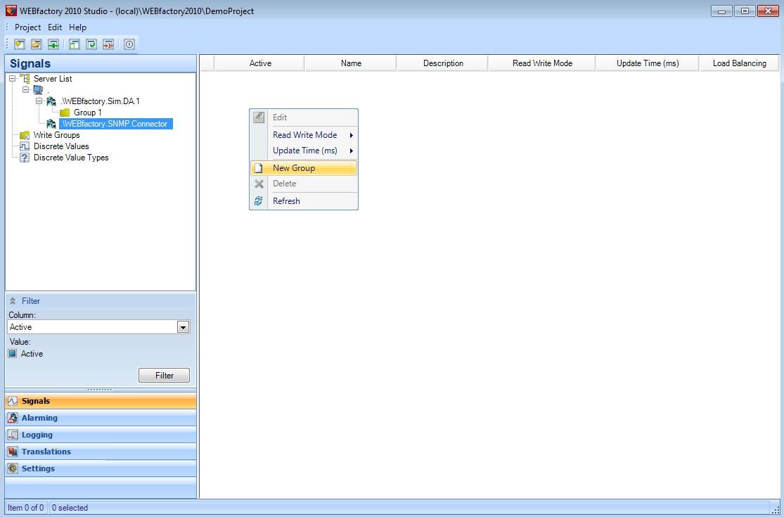
Creating a new Signal Group for the SNMP Connector
Now select the new group Group1 from the Signal tab > Server List > server > Ewon by HMS Networks .SNMP.Connector and right click in the right panel to create a new signal.
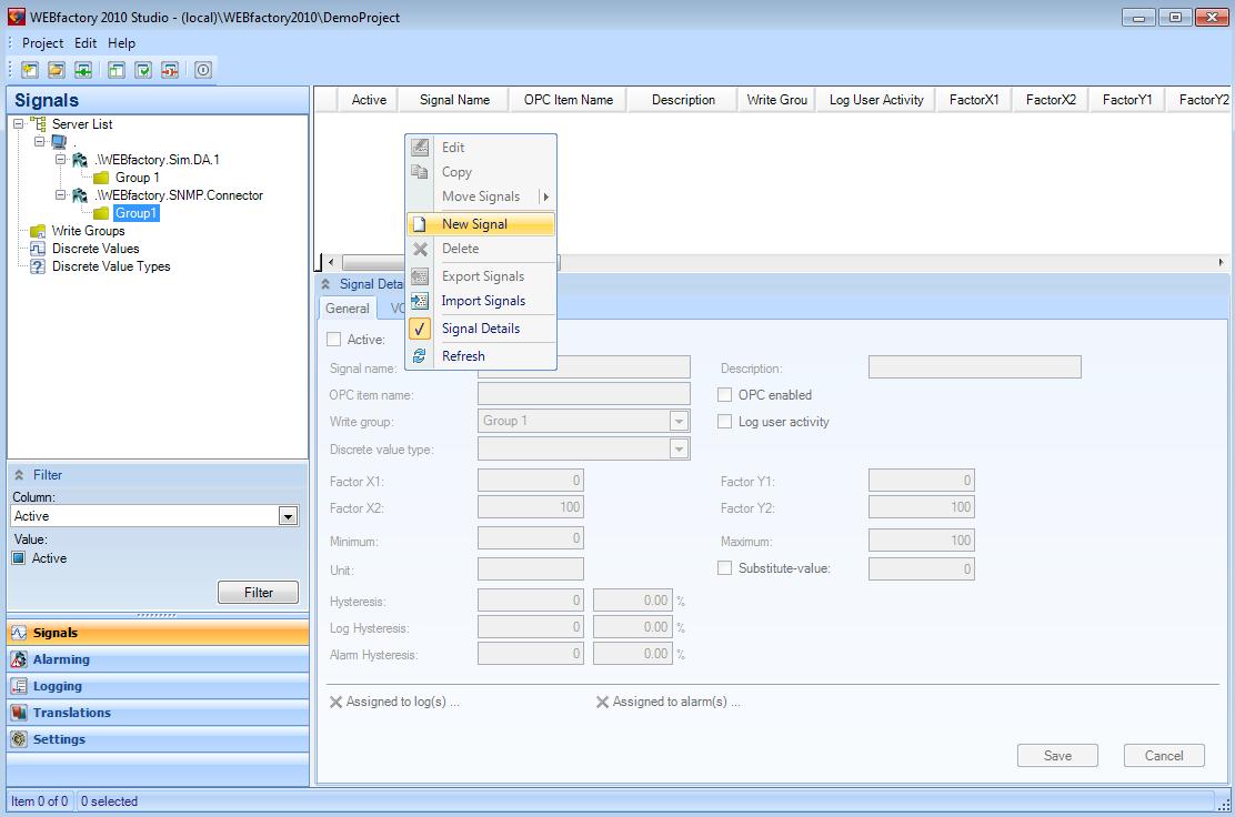
Creating a new signal
In the Signal Details panel, name the signal as My.Processes.
Set OPC item name to My.Processes too.
Click Save to save the signal settings.
Testing the My.Processes signal and the SNMP Connector
To test the result, start the WEBfactory 2010 Server (or restart it if it was running) and open the Ewon by HMS NetworksTest Center.
In the Test Center, import the signal by clicking on Browse server from the top bar.
Select Group1 from the Ewon by HMS Networks .SNMP.Connector and select the My.Processes signal.
Click Import to import it, and Close to close the Browse Server window.
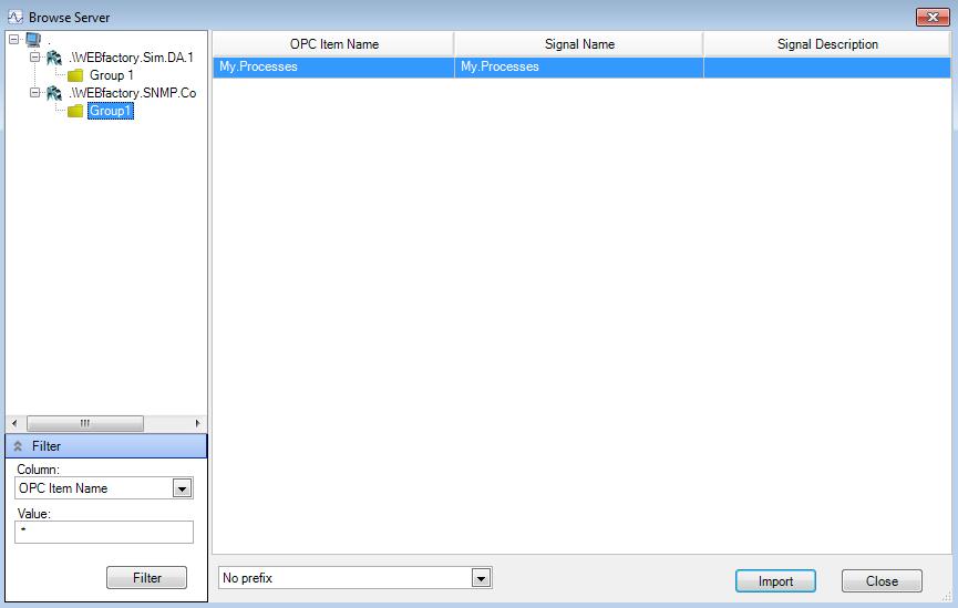
Browse the server and select to import the desired signal in Test Center
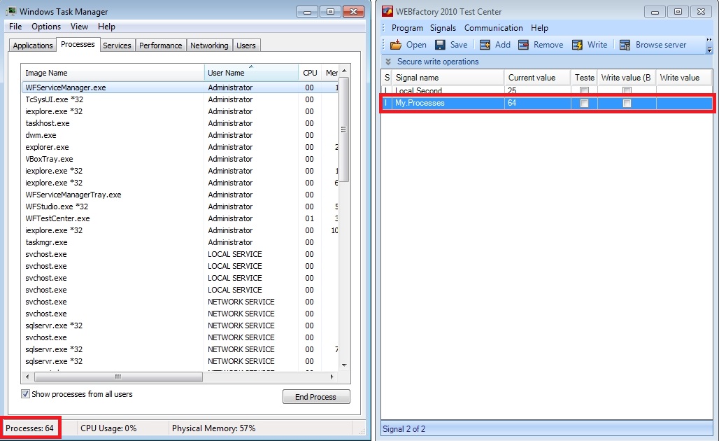
The Test Center should display the right value for the signal. To test the signal against the system, open the Windows Task Manager and check the number of running processes. It will be the same with the one displayed by the My.Processes signal in Test Center.
Modbus Connector Overview and Configuration
Check out this article and get an overview upon the Modbus Conector configuration steps.
The Modbus Connector is integrated in WEBfactory 2010 and is installed by default along with WEBfactory 2010. It has no special system requirements other than the WEBfactory 2010System Requirements.
The Modbus Connector requires a valid runtime license to operate. The license can be obtained using a hardware dongle or by activating the corresponding software license.
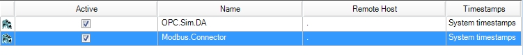
A single Modbus Connector can be attached to the system. A secondary instance of the connector will not be accepted.
The Modbus Connector must run on the same system as the Ewon by HMS Networks Server. Therefore, the Remote Host of the Modbus Connector must be either "." or the name of the PC.
The configuration of the Modbus Connector is done in Ewon by HMS NetworksStudio.
The Modbus Connector Configuration panel allows the user to configure the devices and substations using this connector and the signals associated with the substations.
The Modbus connector configuration panel
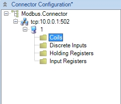
The tree menu will display the Modbus substations. The substations will be structured under a device. Each substation will have it's properties structured in four different groups:
Coils - read/write values
Discrete Inputs - read only values, hardwired to devices
Holding Registers - read/write values on 32 bits
Input Registry - read only items of the device
If right-clicking on any item of the tree menu, the contextual menu will open, allowing the user to add or delete an object (device, substation or signal).
The contextual menu
Note
The contextual menu of the tree menu will list the same options as the menu of the Modbus Connector Configuration panel.
The Filter panel allows the user to filter the signals displayed in the signals grid using the Columns of the main view grid and their Values as filter criteria.
The Modbus Connector Configuration panel menu allows the user to add a new object, delete the selected object and import objects.
UI Option | Description |
|---|---|
New | Adds a new Modbus device, substation or signal. |
Delete | Deletes the selected object. |
Copy | Copies the selected object for the desired amount of times. |
Import | Allows the user to import an XML configuration for the Modbus connector. |
Export | Allows the user to export the current configuration using the XML format. |
When adding a new device to the Modbus connector, the two options of connecting a device are displayed in the New dialog: TCP and RTU.
TCP settings
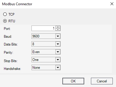
RTU settings
Depending on the selected object in the tree menu, the main view of the Modbus Connector Configuration panel can display one of the following views: the Devices view (if the connector is selected in the tree menu), the Substations view (if the device is selected in the tree menu), the Data Type view (if the substation is selected in the tree menu) or the Signals view (if either one of the substation items is selected in the tree menu).
Devices view
In this view, the main grid of the Connector Configuration panel displays the available devices. The Modbus devices can connect using two different methods: TCP or RTU.
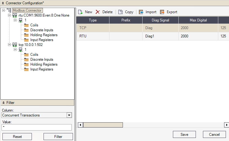
Devices view
UI Option | Description |
|---|---|
Type | The type of connection for the device. Can be TCP or RTU. |
Prefix | The prefix of the device. |
Diag Signal | Diagnose signal |
Max Digital | The maximum number of bit-sized digital data bits that would be placed in one packet. The highest value should be 2000. |
Max Registers | The maximum number 16-bit register data that would be placed in one packet. The highest value should be 125. |
Concurrent Transactions | The number of parallel gateway accesses made by the Modbus protocol. The gateway hosts several devices accessed by Modbus, devices that are distinguished based on their unitID's. |
TCP Address | The address for the TCP connection. |
TCP Port | The port for the TCP connection. |
RTU Port | The port for the RTU serial connection. |
RTU Baud | The rate of symbols changed per second. |
RTU Parity | Parity bit used in detecting errors in transmission. |
RTU Data Bits | The number of data bits in each character. |
RTU Stop Bits | The bits sent at the end of every character in order to allow the hardware to detect the end of a character. |
RTU Handshake | The flow control interaction. |
Substations view
In this view, the main grid of the Connector Configuration panel will display the available substations for the selected Modbus device.
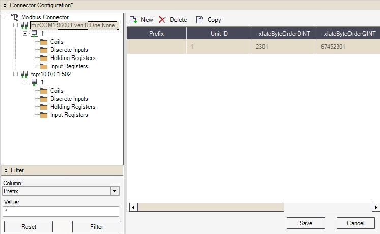
Substations view
UI Option | Description |
|---|---|
Prefix | The prefix of the substation. |
Unit ID | The ID of the Modbus device inside the Modbus network (substation). |
xlateByteOrderDINT | The parameter used to set the bytes order for integer 32 bits values. |
xlateByteOrderQINT | The parameter used to set the bytes order for integer 64 bits values. |
xlateByteOrderREAL | The parameter used to set the bytes order for floating point 32 bits values. |
xlateByteOrderDREAL | The parameter used to set the bytes order for floating point 64 bits values. |
For more information about byte order in Modbus connector, follow this link: Modbus Connector Overview and Configuration - Connecting the Modbus devices
Data Type view
In this view, the main grid of the Connector Configuration panel will list the four types of stored data for the selected substation.
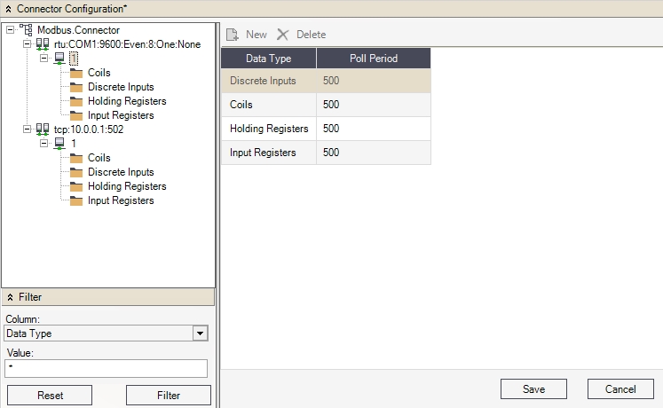
Data type view
UI Option | Description |
|---|---|
Data Type | The type of data represented by associated signals:
|
Poll Period | The polling period of the available data type signals. |
For more information about types of data in Modbus connector, follow this link: Modbus Connector Overview and Configuration - Defining the Modbus device signals
Signals view
In this view, the main grid of the Connector Configuration can display the available signals for the different data types of the substation.
Coils and Discrete Inputs
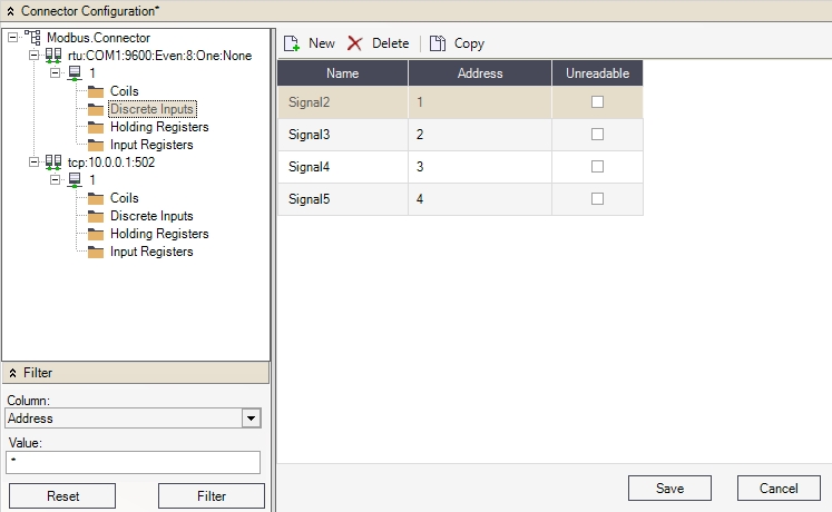
Colis and discrete inputs
UI Option | Description |
|---|---|
Name | The name of the signal. |
Unreadable | If enabled, this signal value will not be available in the server. |
Address | The address of the signal in the OPC Server. |
Holding Registers and Input Registers
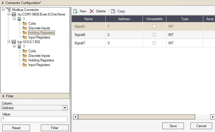
Holding registers and Input Registers
UI Option | Description |
|---|---|
Name | The name of the signal. |
Address | The address of the signal in the OPC server. |
Unreadable | If enabled, this signal value will not be available in the server. |
Type | The signal value type. |
Array Item Size | The size of the array, if the array or array types are selected. |
Adding the Modbus Connector to Variables WEBfactory 2010 Studio
Check out this article in order to learn how to access a Modbus device, the Modbus Connector must be added in Studio.
To enable Ewon by HMS Networks Server to access a Modbus device, the Modbus Connector must be added in Studio.
Right-click on the Server and select New Connector > Modbus Connector.
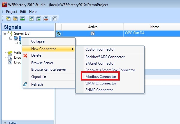
Modbus Connector
Once the Modbus Connector is added, the Connector Configuration panel will be available. All the required configuration will be done here.
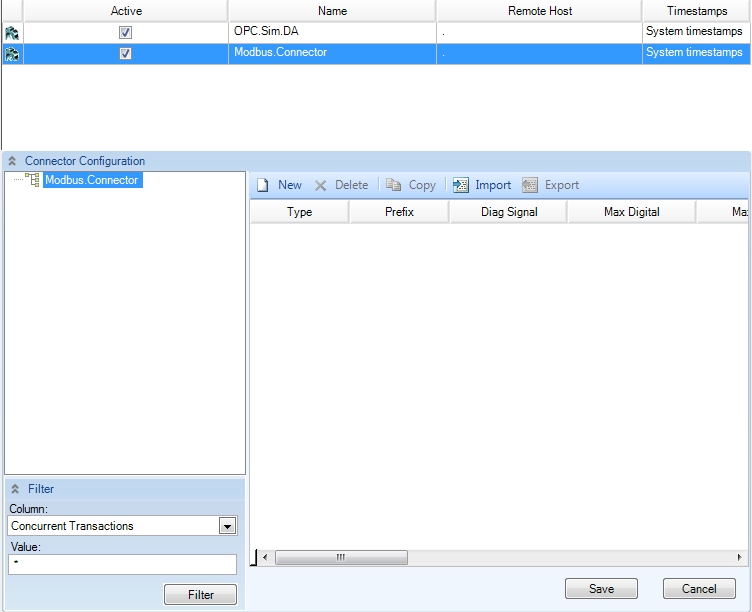
Modbus connector configuration panel
Creating a Modbus communication link
Check out this article in order to learn more details about the Modbus connector communication link.
In order to communicate using the Modbus protocol, a communication link must be defined. The communication link defines the communication type which will be used to reach the Modbus gateway.
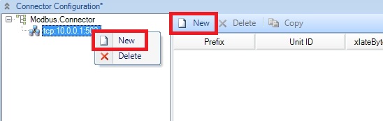
Create a new communication link using the New button from the Connector Configuration panel while the Modbus Connector is selected or right-click on the Modbus Connector from the Connector Configuration and select New.
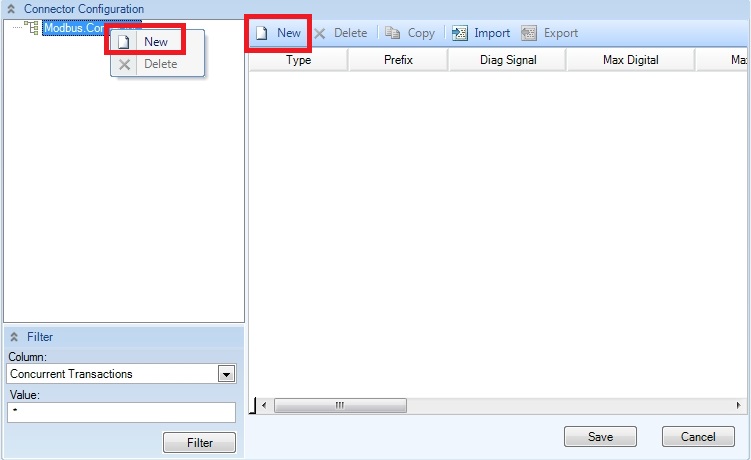
New communication link
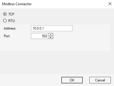
A dialog will ask you to select one of the two available communication protocols: TCP (Ethernet) or RTU (Serial).
For using the Modbus TCP protocol, enter the IP Address and Port of the Modbus gateway machine. The default port number is 502.
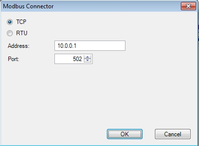
Modbus connector
For using the Modbus RTU protocol, provide the parameters of the serial interface of the Modbus gateway.
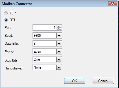
Serial interface parameters of the Modbus gateway
The Port parameter represents the COM port on the PC running the Ewon by HMS Networks Modbus Connector.
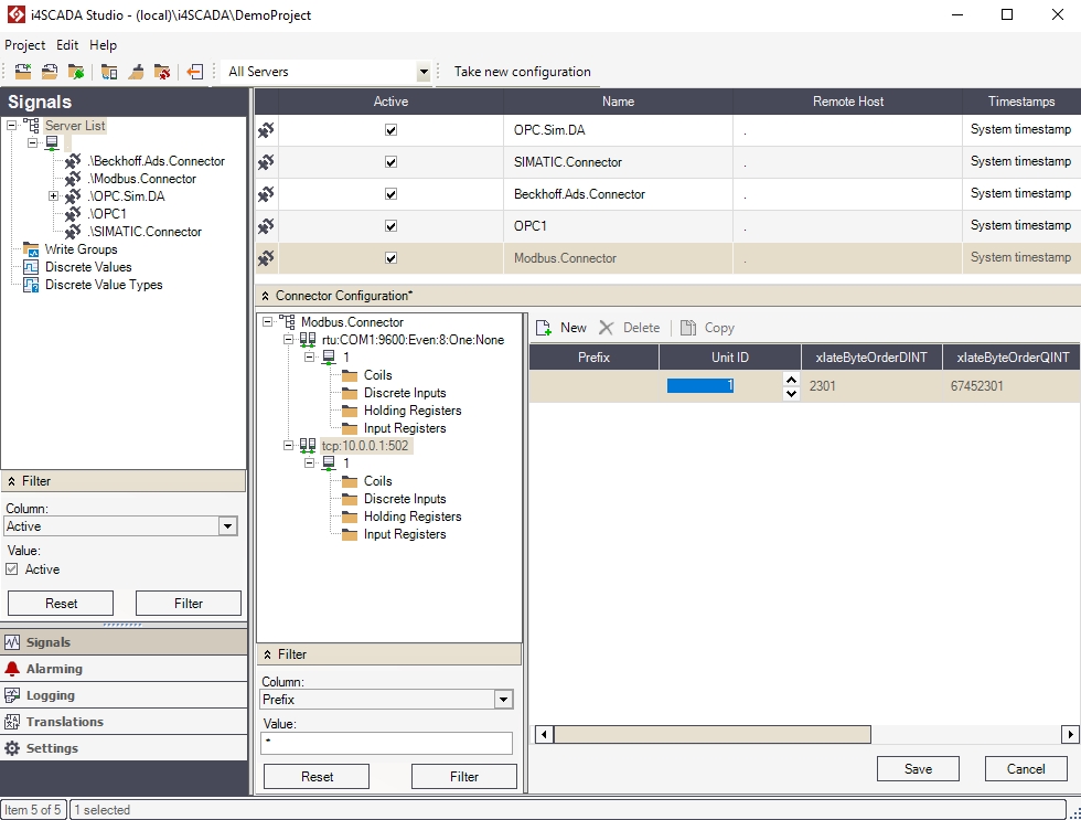
Setting up the connected Modbus gateway
Check out this article and learn more details on how to set up a Modbus gateway in WEBfactory Studio.
After creating the communication link for the Modbus gateway, besides the parameters of the used protocol, the following parameters are available in the Connector Configuration panel.
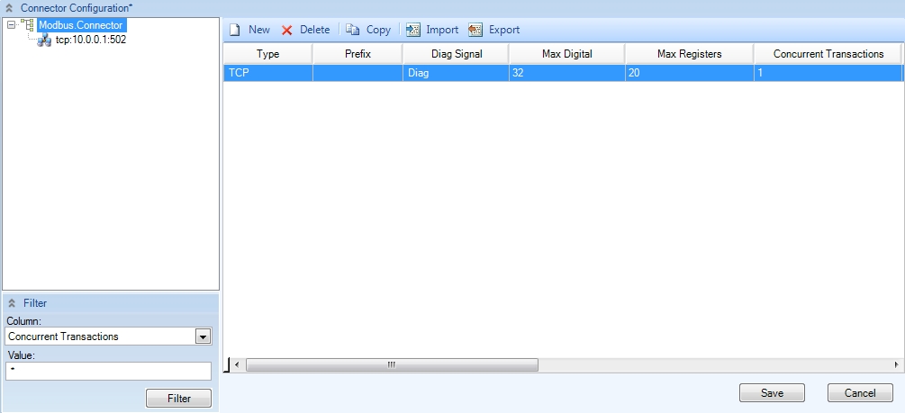
Modbus Connector Configurator
Parameter | Description |
|---|---|
Type | The type of connection for the device. Can be TCP or RTU. |
Prefix | The prefix of the device. |
Diag Signal | Diagnose signal |
Max Digital | The maximum number of bit-sized digital data bits that would be placed in one packet. The highest value should be 2000. |
Max Registers | The maximum number 16-bit register data that would be placed in one packet. The highest value should be 125. |
Concurrent Transactions | The number of parallel gateway accesses made by the Modbus protocol. The gateway hosts several devices accessed by Modbus, devices that are distinguished based on their unitID's. |
TCP Address | The address for the TCP connection. |
TCP Port | The port for the TCP connection. |
RTU Port | The port for the RTU serial connection. |
RTU Baud | The rate of symbols changed per second. |
RTU Parity | Parity bit used in detecting errors in transmission. |
RTU Data Bits | The number of data bits in each character. |
RTU Stop Bits | The bits sent at the end of every character in order to allow the hardware to detect the end of a character. |
RTU Handshake | The flow control interaction. |
Connecting the Modbus devices
Check out this article and learn how to connect the Modbus devices to the gateway.
After setting up the Modbus gateway, the devices must be created and connected to the gateway.
Create a new Modbus device using the New button while the Modbus gateway is selected or using the New button from the gateway's contextual menu.
New Modbus device
The new Modbus device will be connected to the gateway. The following parameters are available for the Modbus device:
Parameter
Description
Prefix
The prefix of the substation. It can be used as a prefix for Signal Names in visualization projects.
Unit ID
The ID of the Modbus device inside the Modbus network (substation).
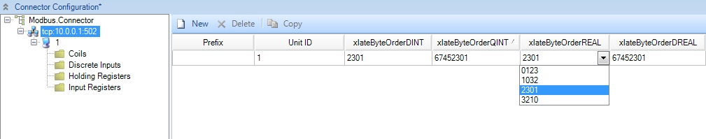
xlateByteOrderDINT
The parameter used to set the bytes order for integer 32 bits values.
The Modbus connector accepts four possible byte order values for 4 bytes data types:
0123
1032
2301
3210
The default byte order value is 2301.
xlateByteOrderQINT
The parameter used to set the bytes order for integer 64 bits values.
The Modbus connector accepts four possible byte order values for 8 bytes data types:
01234567
10325476
67453201
76543210
The default byte order value is 67452301.
xlateByteOrderREAL
The parameter used to set the bytes order for floating point 32 bits values.
The Modbus connector accepts four possible byte order values for 4 bytes data types:
0123
1032
2301
3210
The default byte order value is 2301.
xlateByteOrderDREAL
The parameter used to set the bytes order for floating point 64 bits values.
The Modbus connector accepts four possible byte order values for 8 bytes data types:
01234567
10325476
67453201
76543210
The default byte order value is 67452301.
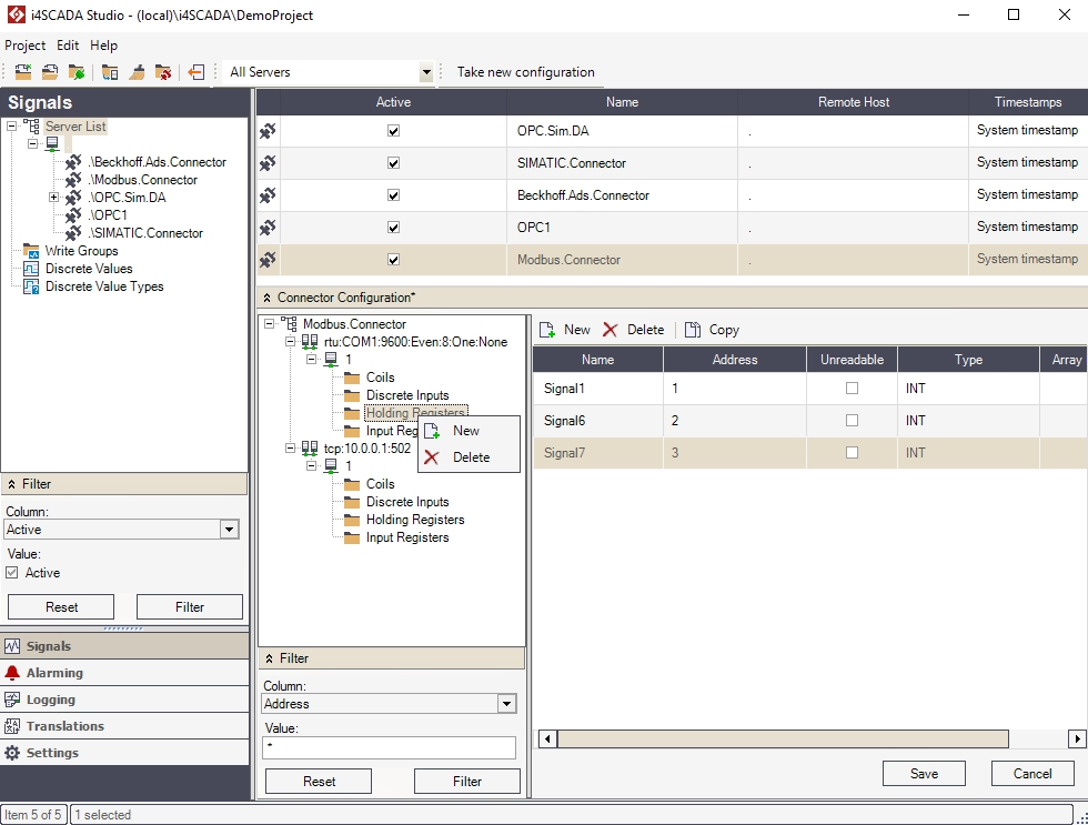
Defining the Modbus device signals
Check out this article and start defining the Modbus device signals in order to be able to use the Modubus connector.
The signals are defined by data stored in Coils, Discrete Inputs, Holding Registers and Input Registers. Each type of data can be defined as a signal.
List of Modbus Signals
The Coils and Discrete Inputs signals must be defined using the Name and Address parameters.
To create a new signal, simply select the type (Coil, Discrete Inputs, Holding Registers, Input Registers) press the New button and enter the required parameters.
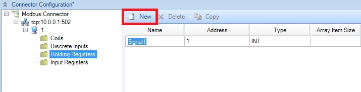
New SIgnal
Accessing the Modbus signals in WEBfactory Studio
Check out this article and learn how to access the Modbus signals in WEBfactory Studio.
The configured Modbus signals can be imported to the items of a connected OPC server using the Studio's signal browser.
To import the signals, create a Signal Group for the Modbus connector.
New Group
Using the contextual menu of the new Modbus Signal Group, use the Browse Connector functionality to look up the Modbus signals.
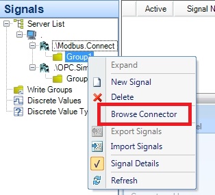
Browse Connector Signals
In the Browse Connector window, select the signals and add them to the Ewon by HMS NetworksStudio.
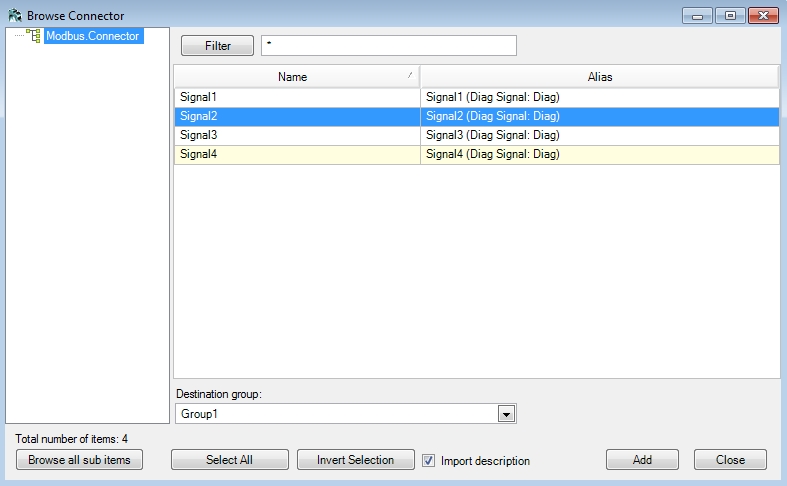
Modbus Signals
The selected signals will be processed by Ewon by HMS Networks Server via the Modbus Connector.
Validating the Modbus signals
Check out this article and learn how to validate your Modbus Connector's Signals.
Ewon by HMS NetworksStudio provides a validation function which helps in determining whether invalid signals have been configured for a specific connector or symbols provided by the connector are not used.
From the Modbus Connector's contextual menu, select the Validate Signals option.
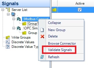
Validate Signals
The Validate Signals will list the invalid signals or unused symbols if they exist.
Validate Signals panel
SIMATIC Connector in Ewon by HMS NetworksStudio
Check out these article and learn everything that you need to know in order to configure and use the SIMATIC Connector.
The Ewon by HMS Networks SIMATIC Connector allows the user to establish communication with all the S7 PLC series, using the S7-TCP/IP channel. In Ewon by HMS NetworksStudio, the SIMATIC Connector can be added in the project using the contextual menu of the server from the Signals tree menu.
Configuring the SIMATIC Connector
Unlike the other connectors available in Ewon by HMS NetworksStudio, the SIMATIC Connector offers a slightly different functionality. While having no Connector Configuration panel in Studio, the SIMATIC Connector allows the user to access its configuration tool from the connector's contextual menu in the Signals tree menu.
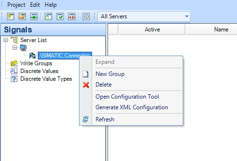
Besides the already familiar options of creating signal groups, deleting the connector or refreshing the list, the SIMATIC Connector contextual menu offers two particular options:
Open Configuration Tool - Opens the SIMATIC connector configuration tool (ACCON-AGLink V4 Configuration)
Generate XML Configuration - Generates an XML configuration based on the settings applied to the SIMATIC connector in Ewon by HMS NetworksStudio.
The user must Generate XML Configuration whenever the SIMATIC connector configuration has been changed!
Using the configuration tool to set up the SIMATIC Connector
The first steps in setting up the SIMATIC Connector will take place in the connector's configuration tool (ACCON-AGLink V4 Configuration).
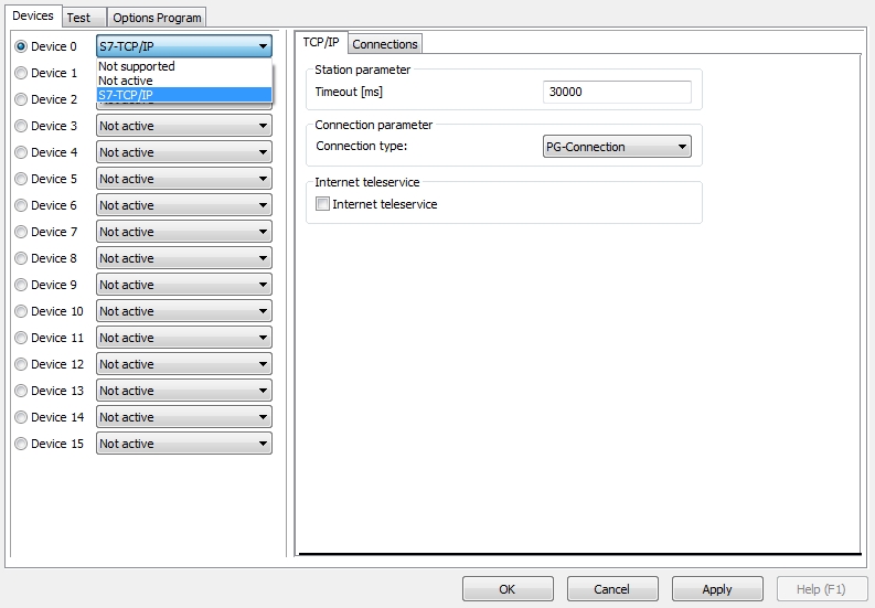
The SIMATIC Connector's configuration tool allows the user to add multiple S7-TCP/IP devices and configure the TCP/IP channel and Connections for every existing device. Once the devices have been set up, the user has the ability to connect different PLCs to the S7-TCP/IP devices, using the Connections panel form the Devices tab.
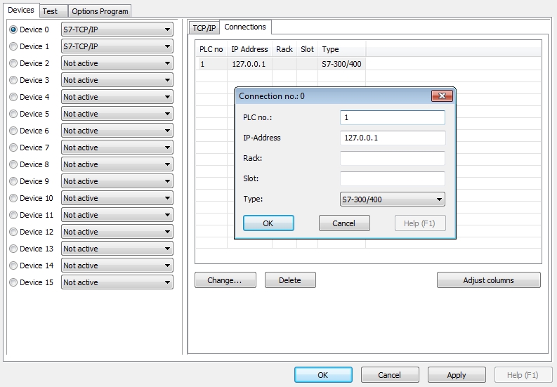
When connecting a PLC to the S7-TCP/IP device, the user must specify the PLC number, the IP address, rack, slot and type. The PLC types that can communicate with the S7-TCP/IP device are:
LOGO!
S7-300/400
S7-200
S7-1200 (Note: Read the PLC documentation for the access settings)
S7-1500 (Note: Read the PLC documentation for the access settings)
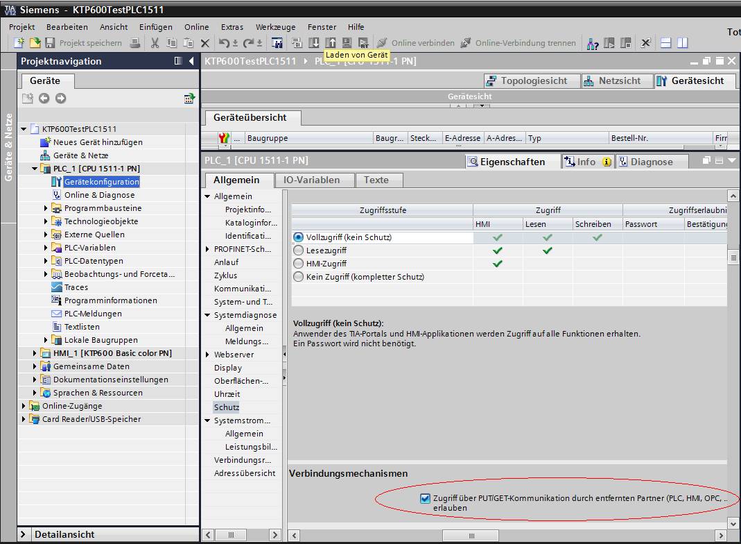
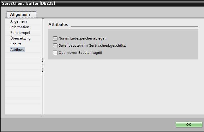
The S7-1200 and S7-1500 PLC requires the following settings in order to operate as expected:
ALLOW Put/Get Communication
DO NOT activate "Optimierter Bausteinzugriff"
The settings done in the SIMATIC Connector's configuration tool will be saved in a predefined location, visible in the Options Program tab.
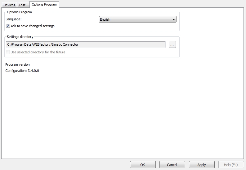
NOTE
The SIMATIC Connector configuration may be copied from one Server to another. To organize this action, copy all files from %ProgramData%\WEBfactory\SimaticConnector from the source server to the destination server.
IMPORTANT
The Device number and the PLC number are crucial in defining the signals inside Ewon by HMS NetworksStudio!
Using the configuration tool to test the SIMATIC Connector setup
The Test tab of the configuration tool allows the user to test a specific PLC connected to the selected Device.
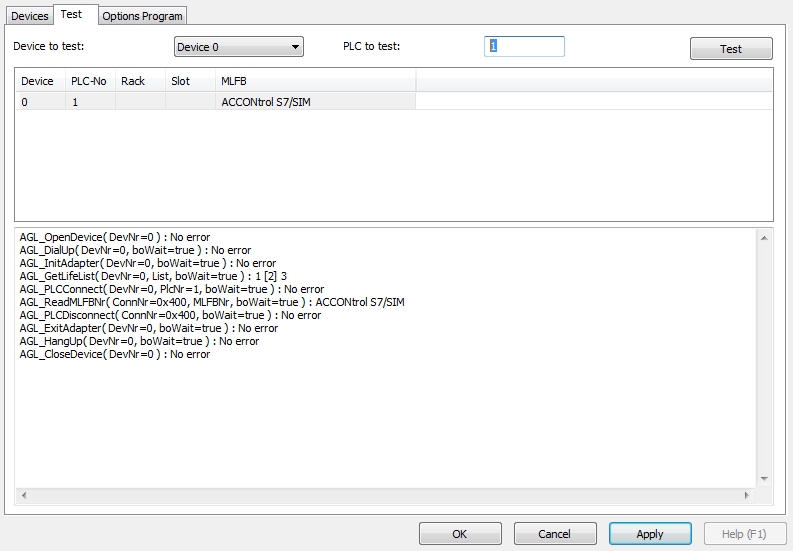
To test a PLC connection, the user must select the desired Device from the Device to test list, specify the PLC number of the PLC that needs testing and click the Test button. If the test succeeds, no error will be displayed in the console and the connected PLC of the Device will be listed in the test grid.
Setting up signals for the SIMATIC Connector in Ewon by HMS NetworksStudio
To set up signals inside Ewon by HMS NetworksStudio for the SIMATCI Connector, a special format must be used in the signal's Connector address. The signal's connector address is composed from three important data:
the Device number - the Device number from the SIMATIC Connector's configuration tool
the PLC number - the PLC number from the SIMATIC Connector's configuration tool
the data type - see list below
The signal's connector address will look like this:
"Device_number"."PLC_number"/"data_type"
"Device_number"."PLC_number"\"data_type"
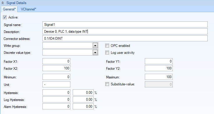
Note that the separator used between the Device_number and the PLC_number will always be "." (dot), while the separator used between the PLC_number and the data_type can be either "\" (back-slash) or "/" (forward-slash).
The following signals will be ignored (a message will be logged in the Activity Analyzer):
virtual signals (VChannel)
duplicate signals having the same Connector address
signals with an invalid format
The Diagnose Signals
The Diagnose Signal is a Counter which counts upwards when a error in SIMATIC communication occurs. Diag Counter is only reset when SIMATIC connector performs a restart.
Syntax for WEBfactory Studio usage:
diag.[Device Number].[PLC Number]
A Diagnose signal is unique based on the Device_number and PLC_number combination.
The Data Types
The following table contains all the supported data types:
Description | Format | Range | Example | Data Type |
|---|---|---|---|---|
Input bit | Ix.y | x:0-65535 y:0-7 | I2.0 | bool |
Input byte / unsigned | IBx | x:0-65535 | IB4 | byte |
Input word / unsigned | IWx | x:0-65534 | IW0 | ushort |
Input word / signed | IWx:INT | x:0-65534 | IW6:INT | short |
Input double word / unsigned | IDx | x:0-65532 | ID4 | uint |
Input double word / signed | IDx:DINT | x:0-65532 | ID4:DINT | int |
Input double word / REAL | IDx:REAL | x:0-65532 | ID4:REAL | float |
Output bit | Qx.y | x:0-65535 y:0-7 | Q2.0 | bool |
Output byte /unsigned | QBx | x:0-65535 | QB4 | byte |
Output word / unsigned | QWx | x:0-65534 | QW0 | ushort |
Output word / signed | QWx:INT | x:0-65534 | QW6:INT | short |
Output double word / unsigned | QDx | x:0-65532 | QD4 | uint |
Output double word / signed | QDx:DINT | x:0-65532 | QD4:DINT | int |
Output double word / REAL | QDx:REAL | x:0-65532 | QD4:REAL | float |
Marker bit | Mx.y | x:0-65535 y:0-7 | M2.0 | bool |
Marker byte / unsigned | MBx | x:0-65535 | MB4 | byte |
Marker word / unsigned | MWx | x:0-65534 | MW0 | ushort |
Marker word / signed | MWx:INT | x:0-65534 | MW6:INT | short |
Marker double word / unsigned | MDx | X:0-65534 | MD4 | uint |
Marker double word / signed | MDx:DINT | x:0-65532 | MD4:DINT | int |
Marker double word / REAL | MDx:REAL | x:0-65532 | MD4:REAL | float |
Time / S5Time | Tx | x:0-? | T0 | string |
Time / BCD | Tx:BCD | x:0-? | T0:BCD | ushort |
Counter / BCD | Cx | x:0-? | C0 | short |
Counter / word | Cx:WORD | x:0-? | C0:WORD | ushort |
Data bit | DBz.DBXx.y | x:0-65535 y:0-7 z:1-65536 | DB54.DBX1.0 | bool |
Data bit - array | DBz.DBXx.y[0..w] | x:0-65535 y:0-7 z:1-65536 w:0-? | DB54.DBX1.0[0..2] | bool[] |
Data byte / unsigned | DBz.DBBx | x:0-65535 z:1-65536 | DB63.DBB12 | byte |
Data byte - array | DBz.DBBx[0..w] | x:0-65535 w:0-(65535 - x) z:1-65536 | DB63.DBB12[0..5] | byte[] |
Data byte / ASCII - array | DBz.DBBx:ASCII[0..w] | x:0-65535 w:0-(65535 - x) z:1-65536 | DB50.DBB0:ASCII[0..4] | string |
Data byte / signed | DBz.DBBx:CHAR | x:0-65535 z:1-65536 | DB63.DBB12:CHAR | char |
Data byte / signed - array | DBz.DBBx:CHAR[0..w] | x:0-65535 w:0-(65535 - x) z:1-65536 | DB63.DBB12:CHAR[0..5] | char[] |
Data byte / STRING | DBz.DBBx:STRING | x:0-65533 z:1-65536 | DB50.DBB0:STRING | string |
Data word / unsigned | DBz.DBWx | x:0-65534 z:1-65536 | DB10.DBW292 | ushort |
Data word / unsigned - array | DBz.DBWx[0..w] | x:0-65534 w:0-((65536 – x) / 2) - 1) ; rounded down z:1-65536 | DB10.DBW292[0..7] | ushort[] |
Data word / signed | DBz.DBWx:INT | x:0-65534 z:1-65536 | DB10.DBW292:INT | short |
Data word / signed - array | DBz.DBWx:INT[0..w] | x:0-65534 w:0 - ((65536 – x) / 2) - 1) ; rounded down z:1-65536 | DB10.DBW292:INT[0..7] | short[] |
Data word / S5Time | DBz.DBWx:S5TIME | x:0-65534 z:1-65536 | DB10.DBW292:S5TIME | string |
Data word / DATE | DBz.DBWx:DATE | x:0-65534 z:1-65536 | DB10.DBW294:DATE | string |
Data double word / unsigned | DBz.DBDx | x:0-65532 z:1-65536 | DB10.DBD24 | uint |
Data double word / unsigned – array | DBz.DBDx[0..w] | x:0-65532 w:0 - ((65536 – x) / 4) - 1) ; rounded down z:1-65536 | DB10.DBD24[0..8] | uint[] |
Data double word / signed | DBz.DBDx:DINT | x:0-65532 z:1-65536 | DB10.DBD24:DINT | int |
Data double word / signed – array | DBz.DBDx:DINT[0..w] | x:0-65532 w:0 - ((65536 – x) / 4) - 1) ; rounded down z:1-65536 | DB10.DBD24:DINT[0..8] | int[] |
Data double word / REAL | DBz.DBDx:REAL | x:0-65532 z:1-65536 | DB10.DBD24:REAL | float |
Data double word / REAL - array | DBz.DBDx:REAL[0..w] | x:0-65532 w:0 - ((65536 – x) / 4) - 1) ; rounded down z:1-65536 | DB10.DBD24:REAL[0..8] | float[] |
Data double word / TIME | DBz.DBDx:TIME | x:0-65532 z:1-65536 | DB10.DBD24:TIME | string |
Data double word / TIME_OF_DAY | DBz.DBDx:TIME_OF_DAY | x:0-65532 z:1-65536 | DB10.DBD24:TIME_OF_DAY | string |
DATE_AND_TIME | DBz.DBBx:DATE_AND_TIME | x:0-65528 z:1-65536 | DB10.DBB300:DATE_AND_TIME | string |