Using the Binary Masks in WEBfactory 2010 Indicator Controls
The BinaryMask option (a logical AND operation between the binary value of the signal and the SignalValue constant) allows the user to use binary values in a WEBfactory 2010 Indicator control (WFIndicator1, WFIndicator2, WFIndicator3 and WFIndicatorDynamic).
Use case
The PLC sends a signal as a WORD with 16 Bits. Each bit represents a separate binary information. For example:
Bit 0 is 1 - Pump A is running
Bit 1 is 1 - Pump B is running
Bit 2 is 1 - Pump C is running
etc.
The user is able to use this single WORD signal to display information about all the Pumps when using the BinaryMask.
Example requirement
Using the information above, the user must set up the WFIndicator1 control to blink with green light when the Pump C is running.
Example solution
Providing the above Use case, Pump C is running when the second bit of the signal is 1. In this case, the following setup is needed:
In WEBfactory 2010SmartEditor, select the WFindicator1 control from the Page or from the Explorer and expand the States property tab.
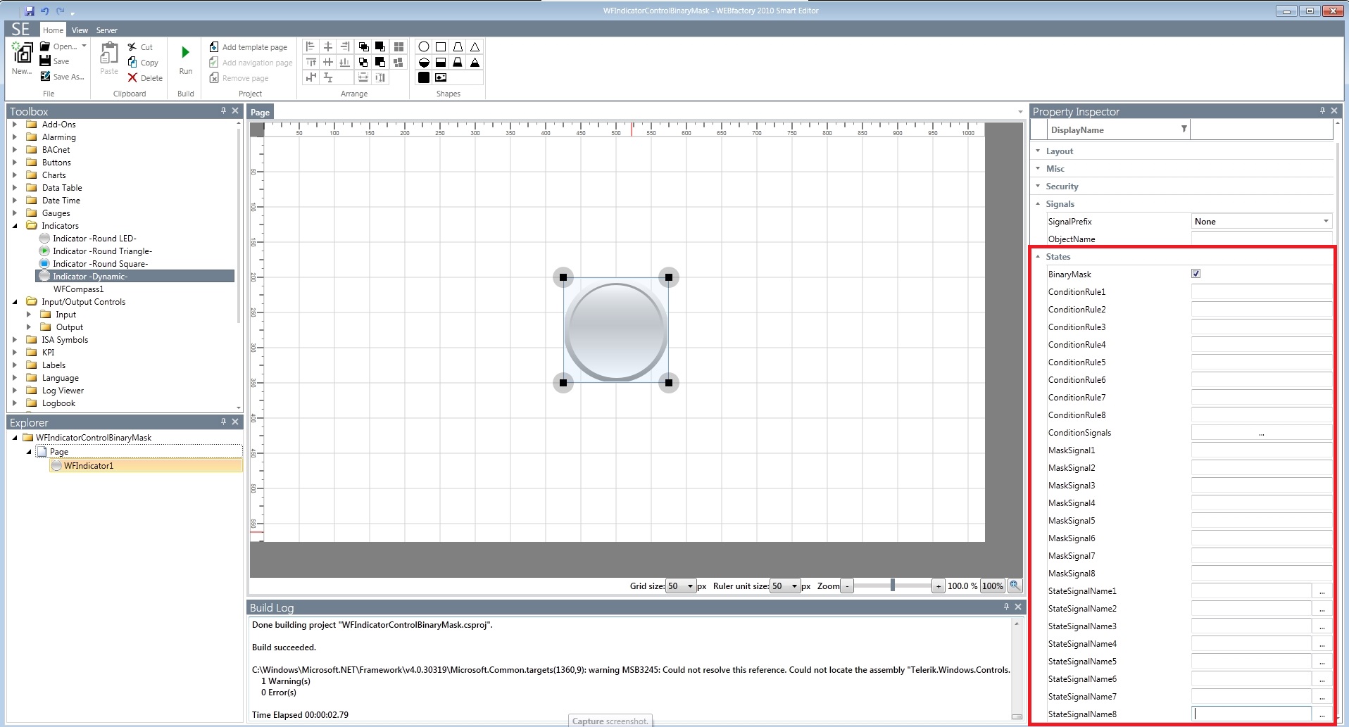
WFIndicator1 in WEBfactory 2010SmartEditor
The WFIndicator1 control provides 8 visual states. The first four states are colored green, red, yellow and blue. The last four states have the same colors (5th state is green, 6th state is red, 7th state is yellow and the 8th state is blue) but the indicator blinks.
More information about the WFIndicator1 control's states here.
As the example requirement asked to set up the WFIndicator1 control to blink green when Pump C is running, the user must use the 5th state of the control.
In the States property tab, check the BinaryMask option. This will allow the user to use binary values for the signals.
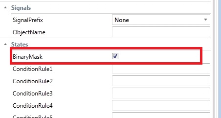
The BinaryMask option must be checked
Enter the desired values in the MaskSignal properties, making sure that the MaskSignal5 property has the decimal value 4.
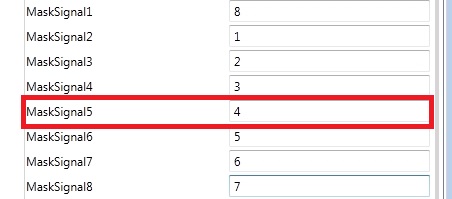
When the third bit is 1, the fifth state will be active
Knowing that when Pump C is running, the second bit of the signal will be 1, the user must use this value as a signal mask for the corresponding state. As the corresponding state is State 5 (green blink), the user must enter the correct value in the MaskSignal5 field. As the second bit must be 1, the correct binary value will be 100 (bit 0 is 0, bit 1 is 0 and bit 2 is 1), or as a decimal, 4.
If the value of the signal is 0, the control will not activate any state, even if the 0 value is set up for one of the eight MaskSignal properties!
Enter the corresponding signal names in the StateSignalName properties. In our example, the signal name will be Setpoint 2 (from the WEBfactory 2010 Demo database).
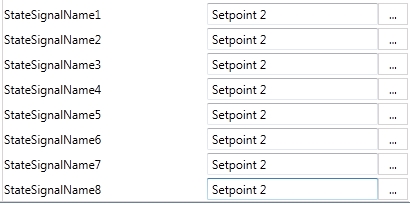
The example signal name
As our PLC is using only one signal to provide information about different devices (the Pumps), all the StateSignalName properties will use the same signal name.
Run the SmartEditor project and open the WEBfactory 2010 Test Center. Load the Setpoint 2 signal in WEBfactory 2010Test Center by browsing the server and write the decimal value 4 to the Setpoint 2 signal. The WFIndicator1 control will enter state 5 and blink with green light.
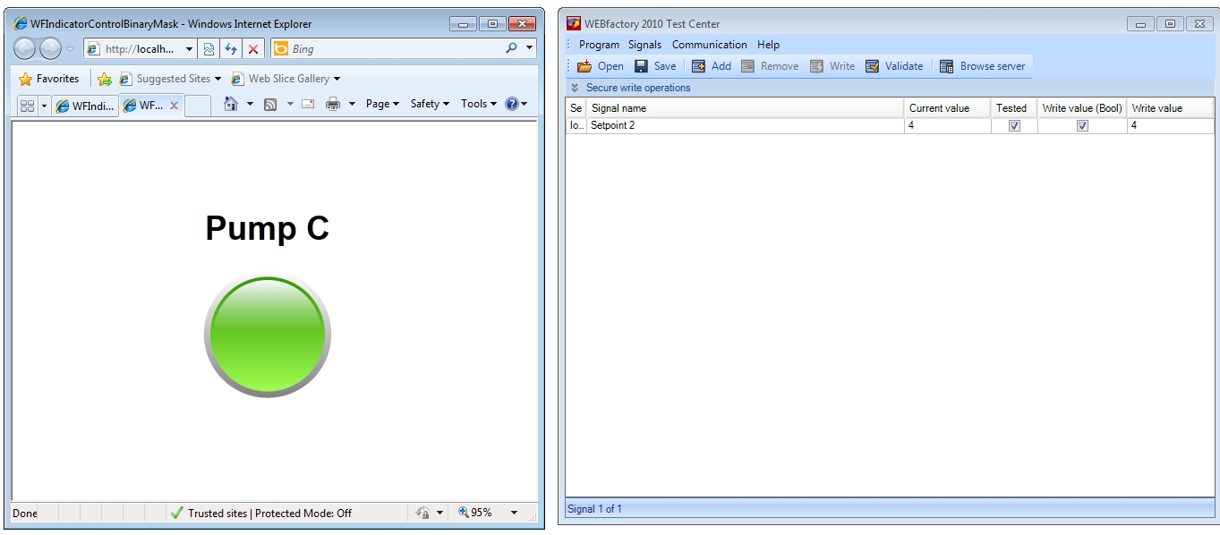
The WFIndicator1 contro, representing Pump C, in the fifth visual state
Because, in our case, the control looks for the third bit (Bit 2) only, any other value that will have the monitored bit equal to 1 will trigger the fifth state of the WFIndicator1 control. For example, values 12 (1100), 13 (1101), 14 (1110) and 15 (1111) will also trigger the same.